watonomous.github.io
[ Electrical Division : Intro to CAN ]
Created by [ Rohan Kumar], last modified on Apr 29, 2020
All the questions you have about CAN answered!
Most of this has been ported from: https://gitlab.com/sibros_public/public/-/wikis/can/can and is copied here for ease of access. Some modifications have been made to more accurately represent the system used in Bolty.
What is CAN?
CAN BUS (Controller Area Network) is a deterministic BUS used heavily in automotive industry. The CAN BUS is used as the primary communication method to the vehicle's electronic control unit which controls the majority if not all of the cars functionality. It is a half-duplex BUS, that operates using a pair of differential signals. Typically, the speed standards are 100K, 250K, 500K or 1Mbit. Bolty is equipped with 3 CAN BUS's namely the High Speed BUS, Chassis Expansion BUS and the Low Speed BUS. The High Speed BUS is responsible for a lot of the control related to the movement and steering of the car. The Chassis Expansion BUS is directly related to the dynamics / physics of the car (torque etc). The Low Speed BUS is responsible for the peripherals of the car: windshield wipers, headlights etc. These run at bitrates of 500K, 500K and 33K respectively. CAN BUS may have several tens of controllers on the same BUS and you can typically go relatively long distances such as 10 meters without compromising the speed or reliability.
Watonomous CAN Source Code
All of our CAN source code can be found in the new remodelled interface: https://git.uwaterloo.ca/WATonomous/can-interface or in the legacy code: https://git.uwaterloo.ca/WATonomous/embedded_actuation_and_controls.
Resources
We have access to a Matlab license which has many CAN debugging tools to visualize CAN signals. We also have a vector CAN license and vector CAN hardware.
Hardware
Termination Resistors
There are two main reason why termination is required. First, it improves signal quality by removing reflections( oscillations) on the bit edges and prevents communication failure. When signal reaches at the end of the cable the reflections become strong, This is the reason why the termination resistors are kept at the ends. Second reason being, to achieve recessive level (defining a logic 1) in the communication.
CAN bus is a serial bus which transmits binary (0(dominant) or 1(recessive)) signals. When CAN Driver at CAN-node transmits recessive bit, it becomes completely passive. A passive component(i.e. resistor) is required as a 'pull-up' or 'pull-down' or both to a certain voltage level to achieve a required signal level during recessive bit transmission.
To protect signal from external noise, twisted pair wire is used as a transmission medium and to get certain voltage level at recessive level, a resistor is placed between two twisted wires. It ensures the required differential voltage level at dominant signal and also brought down the voltage level to zero when dominant signal disappears.
The appropriate resistor selection to define recessive level is a challenge. At the time of dominant signal transmission, achieving certain signal level is desired and the low resistor value demands high current. So, to reduce power consumption, the required resistor value should be higher. Higher resistance value comes with possible drawbacks. if the resistor value is higher, it will demand higher noise energy level to get to the dominant level and a lower noise threshold may prone communication stream to errors. also during dominant signal level the capacitor in the cable gets charged to certain level. So, before CAN-driver can transit from dominant to recessive level the capacitor should get discharged. and Hence, resistor value should be lowest possible for best performance.
As per CAN standard, the typical termination resistor value is kept at 120 ohm. the reason behind this is most of the automotive cables are single wires. if we take wires used in a car and twist them in a pair, the impedance of the twisted pair measures 120 ohms(approx.) and further squeezing the cable the impedance will drop to 105 ohms(approx.). So, as per this the 120 ohm resistance is not the optimal value but it is good enough for slew rate of 50ns at 1 Mbps. The same slew rate with 100Mbps is a problem but the bit rate of 100Mbps is far more than CAN-FD standard.
The termination resistor shall comply with the limits specified in below table:
Notation Unit Value ———- —— —————————– R ~L~ ohm Min: 100 Norm: 120 Max: 130
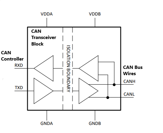
Transceiver
CAN transceivers is an interface between the CAN protocol controller and
the physical wires of the CAN bus lines.
It does mainly two tasks:
- Receiving: It receives differential signal from the bus and converts it to the serial data signal expected by CAN controller. also it has protective circuit to protect the CAN controller.
- Transmitting: It receives serial signal(bits) from the CAN controller and converts it to the differential signal that can be transmitted over typical CAN-bus.
[ {.confluence-embedded-image
height=”250”}]{.confluence-embedded-file-wrapper
.confluence-embedded-manual-size}
{.confluence-embedded-image
height=”250”}]{.confluence-embedded-file-wrapper
.confluence-embedded-manual-size}
Speed and Differential Signals
Bit Stuffing
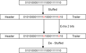
Bit stuffing is technique of adding extra bits to communication packet which does not carry any information but assists in management of communication. It is used to ensure synchronization of all nodes.
During the transmission of a message, a maximum of five consecutive bits may have the same polarity. the transmitter will add an additional bit of opposite polarity in to the bit stream before transmitting new bits.
The receiver also checks for number of bits of same polarity and removes the stuff bit from the bit stream. this is called de-stuffing.
[ {.confluence-embedded-image
height=”221”}]{.confluence-embedded-file-wrapper
.confluence-embedded-manual-size}
{.confluence-embedded-image
height=”221”}]{.confluence-embedded-file-wrapper
.confluence-embedded-manual-size}
This technique is introduced in CAN because of Non Return to Zero(NRZ) coding scheme is adopted. It is used for an entire CAN data or remote frame with the exception of fixed form bit fields for the CRC delimiter, ACK field, and end of frame. CAN error or overload frames are also fixed form.
Any node receiving a message that breaks the bit stuffing rules (more than five consecutive recessive or dominant bits in a sequence that should be bit stuffed) will detect this as a receive error and take action dependant on the node state (for example, transmit an active or passive error frame).
Frame
ACK bit
The ACK bit is located between the CRC delimiter and the ACK delimiter in the CAN frame. The ACK bit is used by any nodes that receive a frame to indicate to the transmitter that it has been received successfully. When transmitting the frame the transmitter transmits a recessive signal (1) in the ACK bit, once a node successfully receives the data it transmits a dominant signal (0) at the ACK bit which overrides the transmitters recessive signal. This signals to the transmitter that the frame was received by at least one node. If you have multiple nodes the dominant signal will always override the recessive signal i.e. If you have two nodes and one signals a dominant ACK bit and the other a recessive ACK bit the dominant value will override the recessive. Thus, the transmitter has no way of knowing that all of the nodes have successfully received the frame. The transmitter will only know that at least 1 has or none of them have.
Message ID based Arbitration
The message ID for a given can frame is also used as the priority of the
message being sent. A lower message ID has a higher priority because
a logical 0 is a dominant signal and will override a logical 1,
which is recessive. When a device starts sending out a message it does
so by transmitting one bit and then observing the bus to see if the same
bit is being sent. If it observes that a different bit is sent it knows
that a higher priority message won the arbitration process and it stops
transmitting. For example, lets say two devices begin transmitting at
the same time. Device 1 is sending a message with id: 0b11000101101
and device 2 is sending a message with id: 0b11000001101. The
following transmission sequence will occur:
Device Start Bit 10 9 8 7 6 5 4 3 2 1 0 Rest of the CAN frame ———- ———– —- — — — — ——- —- —- —- —- —- ———————– Device 1 0 1 1 0 0 0 1 - - - - - No transmission Device 2 0 1 1 0 0 0 0 0 1 1 0 1 ---- Can Bus 0 1 1 0 0 0 0 0 1 1 0 1 ----
As you can see above, device 2 won the arbitration process as its message id is lower than the message id of device 1. Once device 1 did not see the bit that it sent on the bus it knew that it had lost the arbitration process and stopped sending bits altogether after sending bit 5.
RTR
Typically, messages are sent periodically, and asynchronously by the transmitters. In some cases however, a node might want to request data from the transmitter instead of the data being sent periodically. The node can do this by sending a remote frame to the transmitter which triggers the transmitter to send a data frame.
The remote frame and data frame differ in two ways:
- The data frame has the RTR bit set as a dominant signal and the remote frame has the RTR bit sets as a recessive signal
- The remote frame does not include a data field (DLC is set to 0(dominant))
If a data frame and a remote frame are sent with the same message ID then the data frame will simply win arbitration due to the RTR bit (which is the next bit after the ID) being a dominant signal.
Errors
CAN bus is fault tolerant and maintains a number of error counters for robust operation.
Transmit Error Counters
Receive Error Counters
Bus Off Conditions
Applications
- Automotive
- Trucking - J1939
- Industrial
DBC
DBC file is a proprietary format that describes the data over a CAN bus. It is still less proprietary than developing your own standard hence is a good path for CAN applications. Furthermore, manufacturer's of sensors may just provide you the hardware and the DBC file to interface so it is a good format to use.
We will demonstrate the basic syntax of a DBC file that defines up to 8 bytes of CAN message data. A lot of CAN bus related tools can read the DBC file and display values next to each "signal" that you define in the DBC file.
Message Format
DBC file must contain a Message ID (MID), and at least one signal.
Let's demonstrate by showing a message that contains a single 8-bit
signal. Spaces and the syntax is really strict, so if you get a single
space incorrect, the auto-generation script will likely fail.
Example
BO_ 500 IO_DEBUG: 4 IO
 SG_ IO_DEBUG_test_unsigned : 0|8@1+ (1,0) [0|0] "" DBG
Observations:
BO_is a message syntax.- The message name is
IO_DEBUGand MID is500(decimal), and the length is4bytes. (though we only need 1 for 8-bit signal) - The sender is
IO. SG_is a signal syntax.IO_DEBUG_test_unsignedis a signal name.0|8: The unsigned signal starts at bit position 0, and the size of this signal is 8.@1+: Defines that the signal is little-endian, and unsigned.(1,0): Defines scale and offset. (discussed later)[0|0]: Min and Max is not defined. (discussed later)"": There are no units. (it could be, for instance "inches")- The receiver is
DBG.
Signed and Unsigned Signals
A signed signal can be sent by simply applying a negative offset to a signal. Let's add a signed signal to the previous message.
Example
BO_ 500 IO_DEBUG: 4 IO
 SG_ IO_DEBUG_test_unsigned : 0|8@1+ (1,0) [0|0] "" DBG
 SG_ IO_DEBUG_test_signed : 8|8@1- (1,-128) [0|0] "" DBG
Observations
@1-: Defines thatIO_DEBUG_test_signedsignal is little-endian, and signed.
Fractional Signals
A floating point variable can be sent by deciding the range, and the
precision that you require. For example, if we choose 8-bits, with 0.1
as a fraction, we can send the data range of 0.0 -> 25.5. On the other
hand, if we want more precision and negative representation, we could
use 12-bits with 0.01 as a fraction, and an offset. The second
fractional signal also contains an explicit minimum and maximum, which
is limited by 12-bit that can represent 4096 different numbers, and by
factoring in the offset, and using half of the range for negative
representation, it ends up with the limited range of -20.48 -> 20.47.
BO_ 500 IO_DEBUG: 4 IO
 SG_ IO_DEBUG_test_unsigned : 0|8@1+ (1,0) [0|0] "" DBG
 SG_ IO_DEBUG_test_signed : 8|8@1- (1,-128) [0|0] "" DBG
 SG_ IO_DEBUG_test_float1 : 16|8@1+ (0.1,0) [0|0] "" DBG
 SG_ IO_DEBUG_test_float2 : 24|12@1+ (0.01,-20.48) [-20.48|20.47] "" DBG
Observations
- Fractional signal is calculated as: [calculated value] = [offset] + [scale] * [raw value]
- IO_DEBUG_test_float1: variable is calculated as
0 + 0.1 * [raw value]. - IO_DEBUG_test_float2: variable is calculated as
-20.48 + 0.01 * [raw value].
Little Endian Examples
Signals that are defined as Little Endian in the DBC are easier to edit
manually without a UI based DBC editor. This is because when we indicate
that an LSB of a signal is "4" and is a 14-bit signal, then it is
easier to understand the bounds of this signals are b17 ... b4.
Big Endian Examples
Big endian bits are not what they appear to be if you design the DBC manually. It is relatively difficult to design a big endian DBC without a UI based editor. Let us consider some examples:
Example 1
BO_ 504 BIG_ENDIAN1: 8 IO
 SG_ BIG_ENDIAN1_16bit_msb_b0 : 0|16@0+ (1,0) [0|0] "" DBG
The signal that appears to start at b0 actually ends at b0. The
first zero in 0|16@0+ means that the 16-bit Motorolla formatted signal
has its MSB at b0. Have a look at where this signal really fits:
      bit  - 7   6   5   4   3   2   1   0
      ---- +---+---+---+---+---+---+---+---+
         0 |   |   |   |   |   |   |   |<--|
           +---+---+---+---+---+---+---+---+
         1 |-------------------------------|
           +---+---+---+---+---+---+---+---+
         2 |--------------------------*|   |
         | +---+---+---+---+---+---+---+---+
      byte |
To make sense of this, you have to re-arrange the bytes as Big Endian to
form a contiguous signal. The key is to re-arrange the bytes from
byte 0 to byte 2 starting from the left-hand side and spanning the
right-hand side. Now, if you track this 16-bit signal that starts at
bit 1 of byte 2 and go backwards, then you will find the range which
ends at b0 of byte 0.
             <--------- byte 0 ---------->   <--------- byte 1 ---------->   <--------- byte 2 ---------->
             7   6   5   4   3   2   1   0   7   6   5   4   3   2   1   0   7   6   5   4   3   2   1   0
  offset =   0   1   2   3   4   5   6   7   8   9   10  11  12  13  14  15  16  17  18  19  20  21  22  23
           +---+---+---+---+---+---+---+---+---+---+---+---+---+---+---+---+---+---+---+---+---+---+---+---+
           |   |   |   |   |   |   |   |<-m|---|---|---|---|---|---|---|---|---|---|---|---|---|---|-l*|   |
           +---+---+---+---+---+---+---+---+---+---+---+---+---+---+---+---+---+---+---+---+---+---+---+---+
The formula to find the span of this signal is:
- Span the signal from the next byte from high order bit to lower order bit (MSB is left, LSB is right)
- Ending (MSB):
End bit= MSB bit =0 % 8= 0 for0|16End byte= MSB byte =msb_bit // 8(integer division)
- Starting (LSB):
- We calculate an offset which is a bit unique bit counter for all
bytes, see
offsetin the figure above - Let
offset=(8 * (msb_bit // 8) + (7 - msb_bit % 8) + sig_width - 1= 22 Start bit= LSB bit =7 - (offset % 8)= 1Start byte= LSB byte =offset // 8= 2
- We calculate an offset which is a bit unique bit counter for all
bytes, see
Example 2
BO_ 505 BIG_ENDIAN2: 8 IO
 SG_ BIG_ENDIAN2_16bit_msb_b4 : 12|16@0+ (1,0) [0|0] "" DBG
Signal Overlay (byte 0 is omitted):
             <--------- byte 1 ---------->   <--------- byte 2 ---------->   <--------- byte 3 ---------->
             7   6   5   4   3   2   1   0   7   6   5   4   3   2   1   0   7   6   5   4   3   2   1   0
  offset =   8   9   10  11  12  13  14  15  16  17  18  19  20  21  22  23  24  25  26  27  28  29  30  31
           +---+---+---+---+---+---+---+---+---+---+---+---+---+---+---+---+---+---+---+---+---+---+---+---+
           |   |   |   |<-msb--------------|-------------------------------|------lsb-*|   |   |   |   |   |
           +---+---+---+---+---+---+---+---+---+---+---+---+---+---+---+---+---+---+---+---+---+---+---+---+
- Ending (MSB):
End bit= MSB bit =12 % 8= 4End byte= MSB byte =msb_bit // 8= 1
- Starting (LSB):
offset=(8 * (msb_bit // 8)) + (7 - (msb_bit % 8)) + sig_width - 1=8 + 3 + 16 - 1= 26Start bit= LSB bit =7 - (offset % 8)= 5Start byte= LSB byte =offset // 8= 3
Multiplexed Signals
Enumerations
-
Enumeration is a user defined data type. It is primarily used to assign labels to constants to make the logic easy to comprehend and maintain. Enumerated data types are data types consisting of a collection of values called enumerators. These values are comparable, but interpreters and compilers represent them arbitrarily, i.e., they do not have any specific representation in the memory. A variable that has been declared as having an enumerated type can have any of the enumerators as its value.
-
Particularly, in a DBC file format, the user utilizes enumeration to be able to use names instead of numbers to represent states. For example, in a traffic light state machine- the states '0', '1', '2' can be represented as "Red", "Yellow", and "Green" respectively. This can be achieved by adding the following two lines of code in the DBC file.
- A "BA_" field is required, and you can follow the example below to list an enumeration as a "FieldType" first for the sake of simplicity.
- A "VAL_" field is required to define the enumeration values.
BO_ 500 IO_DEBUG: 4 IO
 SG_ IO_DEBUG_test_enum : 8|8@1+ (1,0) [0|0] "" DBG

BA_ "FieldType" SG_ 500 IO_DEBUG_test_enum "Traffic_light";

VAL_ 500 IO_DEBUG_test_enum 0 "Red" 1 "Yellow" 2 "Green";
Miscellaneous
Cycle time, initial values etc
Typical CAN Driver
CAN Frame Structure
Bitrate Settings
A single bit is broken out into these separate time segments:
                    Nominal Bit Time (of one Bit) composed of 8 Tq
               |-------------------------------------------------------|
______________  _______________________________________________________  _________
              \/      |      |                           |             \/
 previous bit || SYNC | PROP |        PHASE SEG 1        | PHASE SEG 2 || next bit
______________/\______|______|___________________________|_____________/\_________
               |                                         ^             |
               |                           Sample Point  | At 75%      |
               +------+------+------+------+------+------+------+------+
                          (Time Quanta Tq)            (6) (2)
- Sync
- During the Sync segment, we expect a bit edge transition
- The Sync segment is always 1 Time Quanta (Tq)
- Prop
- The Propagation segment is used to compensate for delays in the bus lines
- The Propagation segment is always a fixed length Tq
- Phase & Phase 2
- May be shortened or lengthened to help keep the clocks in sync
- The Sample Point takes place between these 2 segments
Sample Point
The sample point is the point where bus levels are sampled. This always takes place between Phase 1 and Phase 2 segments. A sample point of 75% is a common starting point, but busses with high baud rate may require a later sample point.
You should configure the clock prescalar driving your CAN peripheral, and your segment Tq registers such that you can achieve your desired sample point. To make this easier, there are many tools online to do these calculations:
Synchronization
The CAN controller will lengthen or shorten a bit by a maximum number known as Synchronization Jump Width. The integer value of SJW represents Tq. This is typically fine left at default value.
Mailboxes
Hardware Filters
Filtering is a way to choose which messages to intercept from the CAN bus. The biggest confusion here is that as soon as your CAN is initialized, it will automatically ACK the frames for ALL frames. So just because you do not intercept a frame does not mean your CAN peripheral will not acknowledge
CAN Tools
PCAN
Bus Master
Vector
References
Cantools
Cantools is an awesome Python tool with so many features such as:
- Parse DBC
- Generate encode and decode functions
- And much more
We used it to generate the signal overlay of the CAN bytes, using the
command cantools dump your.dbc. It is very well written and highly
recommended than writing your own DBC parser.
Bit Time Calculation
This article can be used to calculate the baud-rate register settings for various different CAN peripherals.
\
\
\
Attachments:
![]() Transceiver.png (image/png)
Transceiver.png (image/png)
![]() Untitled_Diagram.png (image/png)\
Untitled_Diagram.png (image/png)\
Document generated by Confluence on Nov 28, 2021 22:40