watonomous.github.io
[ Electrical Division : Radar Signal Definitions ]
Created by [ Rowan Dempster], last modified by [ Frank Yan] on Apr 17, 2020
Table of Contents
Document Abstract
The purpose of this document is to help define the different signal settings the radar can have.
The main signal settings the radar group uses are:
- Azimuth angle
- Mix/max distance
- Velocity threshold
- RCS threshold
- SNR threshold
The other signal definitions are set to their default configuration and are not being used as of now. For more information on all the signal definitions for our radars check the PDF linked below.
[[[]{.companion-edit-button-placeholder
.edit-button-overlay data-linked-resource-container-id=”1442164”
data-linked-resource-id=”1442165” data-template-name=”companionEditIcon”
data-source-location=”embedded-attachment”}]
Purpose
For filtering purposes, configuring the signal settings will help the radars filter out noise and pick up moving objects. All of our settings are defined in the processPacket.h file in the include folder of our repo.
processPacket.h filter thresholds
#define SNR_THRESHOLD            3 //dBr
#define VELOCITY_LOWER_THRESHOLD 0.0 // m/s
#define RCS_THRESHOLD            -20 //(dBm)^2
#define DISTANCE_MAX_THRESHOLD   20 //m
#define DISTANCE_MIN_THRESHOLD   0.0 //m
#define AZI_ANGLE_0_THRESHOLD      -1.44862 //radians, 75 degrees; Azi Angle 0 is the angle from the left center
#define AZI_ANGLE_1_THRESHOLD      1.44862 //Azi Angle 1 is the angle from the right center, positive according to Conti
To do any task related to filtering, understanding what these thresholds will be helpful as we will drop points according to these thresholds defined in the header file. The code for dropping points can be found in the processPacket.cpp file in the src folder.
Code Block where points are dropped
 if (oldMsg->Detections[i].SNR < SNR_THRESHOLD) { // Too much noise; drop detection.
            continue;
        } else if (abs(oldMsg->Detections[i].VrelRad) < VELOCITY_LOWER_THRESHOLD) {
            continue;
        } else if (oldMsg->Detections[i].posX > DISTANCE_MAX_THRESHOLD) { // need to do trig
            continue;
        } else if (oldMsg->Detections[i].posX < DISTANCE_MIN_THRESHOLD) {
            continue;
        } else if (oldMsg->Detections[i].RCS0 > RCS_THRESHOLD) {
            continue;
        } else if (oldMsg->EventID == FAR1 || oldMsg->EventID == FAR0) {
            //limit far scan to 9 degrees, according to conti
            if (oldMsg->Detections[i].AzAng0 < -0.15708 || oldMsg->Detections[i].AzAng1 > 0.15708) {
                continue;
            }
        } else if(oldMsg->Detections[i].AzAng0 < AZI_ANGLE_0_THRESHOLD || oldMsg->Detections[i].AzAng1 > AZI_ANGLE_1_THRESHOLD){
            continue;
        }
Definitions
Azimuth Angles:
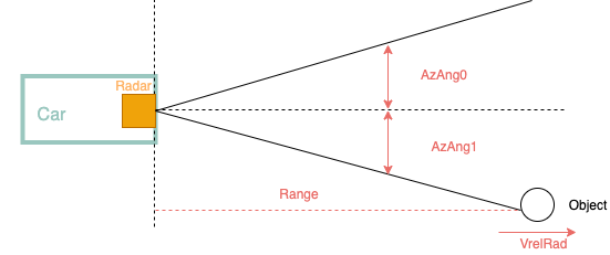
Azimuth angles are the angles that are used to determine the field of view lines for the radars. These angles exist in the x-y plane and are perpendicular to the z axis. The diagram below gives a more clear description of where the azimuth angles are. The diagram is drawn from a bird's eye view perspective so the azimuth angles lie on the x-y plane or the ground, if you're thinking about this in 3D.
\
[ {.confluence-embedded-image
height=”231”}]{.confluence-embedded-file-wrapper
.confluence-embedded-manual-size}
{.confluence-embedded-image
height=”231”}]{.confluence-embedded-file-wrapper
.confluence-embedded-manual-size}
AzAng0 is the angle that is to the left of the radar and is considered to be negative. AzAng1 is the angle to the right of the radar and is considered to be positive. This is the convention that Continental uses. What this threshold does is that if an object is outside the defined range for either AzAng0 or AzAng1, then that object will not be noticed by the radars. For example if the AzAng0 threshold is 75 degrees and an object is 85 degrees from the radar, then that object is not detected. Both the AzAng0 and AzAng1 are measured in radians.
Distance:
Distance thresholds are straightforward as any objects that are not in the distance threshold will not be picked up. To give an example, if the minimum distance threshold is 0.3 m then any object that is less than 0.3 m away from the radars will not be detected. This is the same with the maximum distance threshold where any object that is beyond the maximum distance threshold will not be detected by the radars. Both the minimum and maximum distance thresholds are measured in metres and are measured along the x-axis.
Velocity Threshold:
The technical name for this setting is VrelRad and the technical definition can be found in the above PDF. For our purposes, all you need to know about this threshold is if an object does not have a velocity that is greater than or equal to the defined threshold, that object will not be detected. Setting this setting to a value above zero will filter out static objects and will only pick up moving objects. This is measured in m/s.
RCS Threshold:
RCS stands for Radar Cross Section. RCS describes how well the radar's signals are reflected back. Measured in dB (decibels), increasing this threshold (making the number more negative) will make it harder for objects to be detected as this means that the objects will need to reflect back at least the same level of intensity of the initial radar signal. Decreasing the RCS threshold (making the number closer to zero), will pick up more objects as the objects that the radar signals hit will have an easier time returning the signal back to the radar. Of course, there are many factors that can influence the RCS such as the material of the objects being detected and the surface area of the object. For example, a dog will return a different RCS intensity than a person walking. Another thing to note is that RCS is dependent on the azimuth angles. Azimuth angles will influence the range of the radar signals and will influence how many radar signals are reflected back within that range. Currently, an RCS of -20 to -30 is a good range that will filter out static objects and noise, and pick up moving objects easily.
SNR Threshold:
SNR stands for Sound to Noise Ratio. Continental defines SNR as "the ratio of power of the reflected signal to the power of the reflected background noise". This setting is in dBr (decibels relative to reference level). Very little testing has been done with this, so doing further experiments with the SNR threshold needs to be done to see if this threshold will help or not.
\
Attachments:
![]() RDI_Signal_Definition_v1.00.pdf-Arjunax980.pdf
(application/pdf)
RDI_Signal_Definition_v1.00.pdf-Arjunax980.pdf
(application/pdf)
![]() RadarAziAng.png (image/png)\
RadarAziAng.png (image/png)\
Document generated by Confluence on Nov 28, 2021 22:40