Compliant Control for the Tendon Hand
Goal: try the impedance controller out in simulation before it touches hardware. Check it actually works, add what it turns out to need (friction feedforward, a torque cap, the wrist angle), and catch problems like the wrist early, so the bench work is just system ID: measuring a few numbers, not debugging the controller.
Each finger holds a target angle and stays soft: it pushes with a force you set and gives way when pushed. It needs only the motor encoders and the wrist angle. All results are from simulation in MuJoCo.
The hand
Four motors per finger, one cable each, named by job: f1 spread, f2 MCP, f3 curl, f4 straighten. A spring pulls the spread back against f1. The spread yoke is the knuckle piece the finger swings sideways on, with a short lever on each side: one for f1, one for the spring. A cross-cable makes DIP follow PIP.

| Part | Runs | Ends on | Job |
|---|---|---|---|
| f1 | palm side, thumb edge | spread yoke, thumb-side lever | turns the spread toward the thumb, against the spring |
| spring | pocket in the palm plate | spread yoke, opposite lever | pulls the spread back (18 N preload) |
| f2 | palm side, beside f3, over the MCP | proximal link | flexes the MCP |
| f3 | palm side, centre, over MCP, PIP, DIP | fingertip | curls the PIP + DIP |
| f4 | back, over MCP, PIP, DIP | fingertip | straightens the PIP + DIP and the MCP |
| cross-cable | closed loop, PIP to DIP knuckle | no motor | holds DIP = PIP |
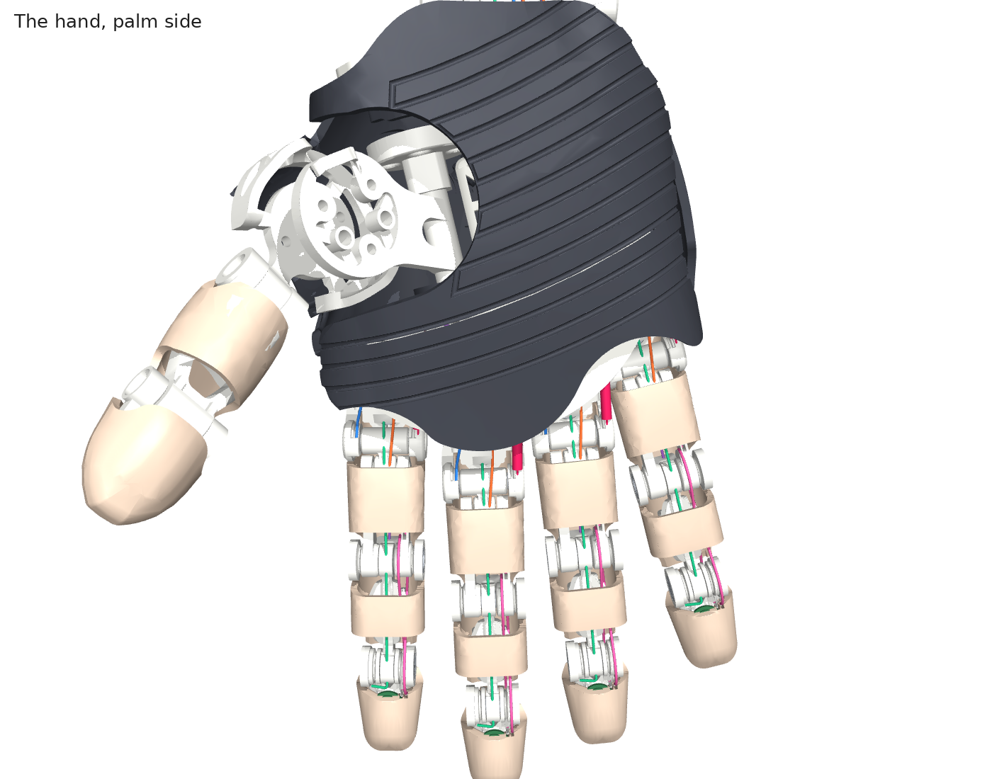
The hand, palm side. Skin, skeleton and palm casing from the hand's CAD; each cable shows in its own colour at the knuckles. The forearm motors are off the top.
How it's simulated
MuJoCo physics, built from the CAD's own geometry: change a cable route in the CAD and the simulation changes with it.
| Part | In the simulation |
|---|---|
| Shape and cables | The CAD's joint axes and every cable route, point by point; the CAD parts as the shapes. Cables are elastic (60 N/mm) and go slack below their rest length. |
| Motors | Each GL30 + gear + spool is a 1.33 kg slider on its cable, pushed by a force capped at 176 N. Commands arrive 1 ms late. |
| Friction | 1.5 N + 0.1 × tension on each spool, with a model that lets a slow spool stick. |
| Spring, cross-cable, wrist | Spring: 1.5 N/mm, 18 N at the straight finger. Cross-cable: modelled strand by strand on one finger, as a DIP = PIP tie in the hand. Wrist and thumb root: position-controlled. |
| Timing | Physics every 0.2 ms. The controller runs every 1 ms and sees only spool encoders, wrist angles and its own commands. |
Two models: one finger to design and stress-test the controller, and the whole hand (20 cables) to check it works with shared wrist and objects.
How the controller works
Every 1 ms, per finger:
- Estimate the joint angles (spread, MCP, curl) from the four spool positions, using the cable-length model and the wrist angle. Assume each cable's stretch from 4 N (f1: from the spring's pull), never from the tension just sent.
- Compute a joint torque: τ = clip(K (target − q), ±τ_max) − D q̇. K = 0.3 / 1.5 / 0.8 N·m/rad, τ_max = 0.15 / 0.4 / 0.25 N·m (spread / MCP / curl). Targets stay 4° inside the stops; D is capped by rate and latency.
- Split the torque into four tensions. f2–f4 share MCP and curl, the slackest at 4 N, none above 50 N. f1 takes what the spread needs after the spring.
- Send the tensions as motor current, plus friction feedforward (1.5 N + 0.1 × tension).
The firmware version uses fitted polynomials for the cable model (0.02 mm) and runs in portable C in 2–3 µs per step. C, Python firmware and the reference agree to 0.01°.
The method in pseudocode
Four parts: build the finger, run the physics, run the controller, add the grasp.
1. Build the finger
What it does: turns the CAD into a MuJoCo model, once.
cad = load_finger_geometry()        # joint axes, links, every cable's route points, the spring's ends

for body in [forearm, wrist, hand, spread_yoke, proximal, middle, distal]:
    model.add_body(body, joint_axis=cad.axes[body], shape=cad.part[body])   # CAD parts, used for contact

for cable in [f1, f2, f3, f4]:
    spool = model.add_slider(along_forearm, inertia=1.33)        # the motor, as felt at the cable (kg)
    model.add_motor(spool, force_limit=176)                       # pulls with the force asked for (N)
    path = [spool] + [point_on(body, p) for body, p in cad.route[cable]] + knuckle_wraps(cable)
    model.add_cable(path, stiffness=60_000, rest=length(path, straight_finger))   # stretchy, can't push

model.add_cable([point_on(hand, A), point_on(yoke, B)], stiffness=1_500, preload=18)   # the spread spring
model.add_constraint(DIP == PIP)                                  # the cross-cable
- Cable lengths come free. MuJoCo measures each cable along its points and over the knuckles, so bending any joint, the wrist included, changes the lengths by itself.
2. Run the physics
What it does: steps the physics every 0.2 ms and calls the controller every 1 ms, with real-world flaws added.
queue = [0] * latency           # commands arrive this many periods late
z = zeros(4)                    # friction state, one per spool

for step in range(duration / 0.2e-3):                  # physics every 0.2 ms
    if step % 5 == 0:                                   # controller every 1 ms
        x  = spool_position() * scale_error + zero_error + noise     # what the encoders read
        xd = spool_velocity()
        u  = controller.step(x, xd, wrist_angles(), target(t))      # never sees the true joint angles
        queue.append(u);  motors.set(clip(queue.pop(0), -176, 176) * torque_error)
        friction_level = 1.5 + mu * cable_tensions()    # a cable pulled harder rubs harder

    v = spool_velocity()                                # friction that sticks when slow, slides when fast
    z = (z + v * dt) / (1 + sigma0 * abs(v) * dt / friction_level)
    spool_friction = -(sigma0 * z + sigma1 * dz_dt)

    apply_test_forces()                                 # a probe, a push on the tip, a tug on the bar
    physics_step()                                      # motors, cables, spring, gravity, contact
- Late commands: the queue delays each command 1–3 periods, as on a real driver (E4, E11).
- Imperfect motors:
scale_error,zero_error,torque_errorand noise make the encoders and motors slightly wrong for the robustness test (E11). Normally 1, 0, 1 and 0. - Sticky friction: a slow spool sticks, which is what costs accuracy. MuJoCo's own friction creeps instead, so it isn't used.
- Every experiment is this loop with a different setup: target, block, probe, wrist swing or a flawed finger.
3. The controller
What it does: every 1 ms on the motor driver: spool positions in, four motor forces out.
# dl(q, wrist): each cable's length change from the straight finger (fitted polynomials)
# R(q): how much each cable moves per joint degree (4 cables x 3 joints)
def step(x, xd, wrist, target):
    # 1. where are the joints? (spread, MCP, curl) from the spools
    stretch = [spring_pull(q) / k, 4 / k, 4 / k, 4 / k]      # assumed cable stretch
    measured = -x + stretch
    for _ in range(2):                                       # two refinement steps from last time
        q += solve(R.T @ R, R.T @ (dl(q, wrist) - measured))

    # 2. how hard to push: a spring and a damper, capped
    q_dot = solve(R.T @ R, R.T @ xd)
    tau = clip(K * (target_inside_stops - q), -tau_max, tau_max) - D * q_dot
    #     K = 0.3 / 1.5 / 0.8 N·m/rad, tau_max = 0.15 / 0.4 / 0.25 N·m

    # 3. which cables pull how hard
    t = tau - spring_tau(q)                                  # the spring already does part of the spread
    R3 = R[f2..f4, MCP..curl];  n = cross(R3 columns)        # n: pulling all three this way moves nothing
    f234 = least_tension(R3, t[MCP..curl]) + lift * n        # slackest at 4 N, none over 50 N
    f1 = (t[spread] - R[f2..f4, spread] @ f234) / R[f1, spread]
    f = [f1, *f234]

    # 4. add friction feedforward, send
    u = f + (1.5 + 0.1 * f) * sign(direction each spool should move) - c * internal_spool_motion
    return u                                                 # the driver turns this into motor current
- Cable stretch is a fixed guess (4 N of pull; f1: the spring's pull), not the force it just sent, so its output never feeds back into its own estimate.
- The cap (
tau_max) is what limits grip force (E9). - No cable goes slack: the spare direction
nlifts the slackest cable to 4 N.
4. The grasp
What it is: a three-state machine on top of the controller. Each state only sets the target and the cap.
| State | Target | Cap | Leaves when |
|---|---|---|---|
| Open | open hand | normal | the robot says "grasp" |
| Closing | a curled pose | low: gentle first touch | push felt and finger stopped for 30 ms |
| Holding | 25° past where it stopped | the grip asked for | the robot says "release" |
if state == CLOSING:
    target, tau_max = curled_pose, low_cap
    if sensed_push(MCP) > 50 N·mm and joints stopped for 30 ms:   # push felt from the motor commands (E13)
        state, contact_pose = HOLDING, q                            # the arm can lift now
if state == HOLDING:
    target, tau_max = contact_pose + 25°, grip_torque              # always past the object, so grip = cap
Why 25° past: the spring is always stretched to the cap, so the grip equals the cap on any object size. Lifting is the arm's job; the hand just stays in Holding.
The spread spring
f1 pulls one lever of the spread yoke, the spring the other. One motor steers the spread both ways, at any curl.
- Measure the spring before fitting it. The controller subtracts the spring's modelled torque (158–188 N·mm). A spring off its spec leaves a fixed spread offset: up to 6.4° (E11).
- It never goes slack. 14–22 N over the ±15° range.
Spec to buy: extension spring, OD ~3 mm, 1.5 N/mm, 18 N at 29.4 mm hook to hook.
One finger
The middle finger on its own, running the joint impedance. Some tests compare it with a stiff servo: the usual tendon-hand control, which drives each motor to a set cable position as hard as it can. No impedance, no give.
Why the PIP and DIP are tied together
Without the cross-cable the DIP collapses (left); with it, the DIP follows the PIP (right).
Test: the same moves twice, with the DIP free and with it tied to the PIP.
The cross-cable is required, for three reasons:
- The curl cables can't hold a pose alone. f3 and f4 both run over the PIP and DIP to the tip, so they set only PIP + DIP. The split is unstable: one joint runs to its stop at every target.
- Return springs don't fix it. A spring on either joint only picks which one fails.
- It matters when grasping too. Untied, the DIP folds over a 24 mm rod and the contact chatters; tied, the finger wraps it cleanly.
To build it: Dyneema, ~20 N pretension, crimps rated ≥ 70 N.
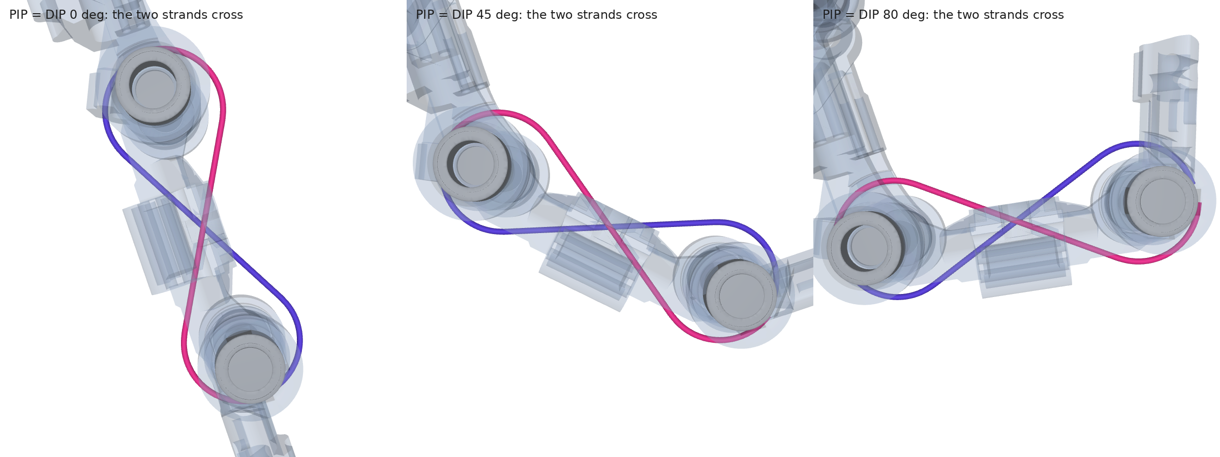
The cross-cable in the CAD. Two strands in grooves on the PIP and DIP knuckles, crossing between them, at 0, 45 and 80°. One winds on as the other winds off, so the DIP turns with the PIP.
E4 · how fast the loop must run
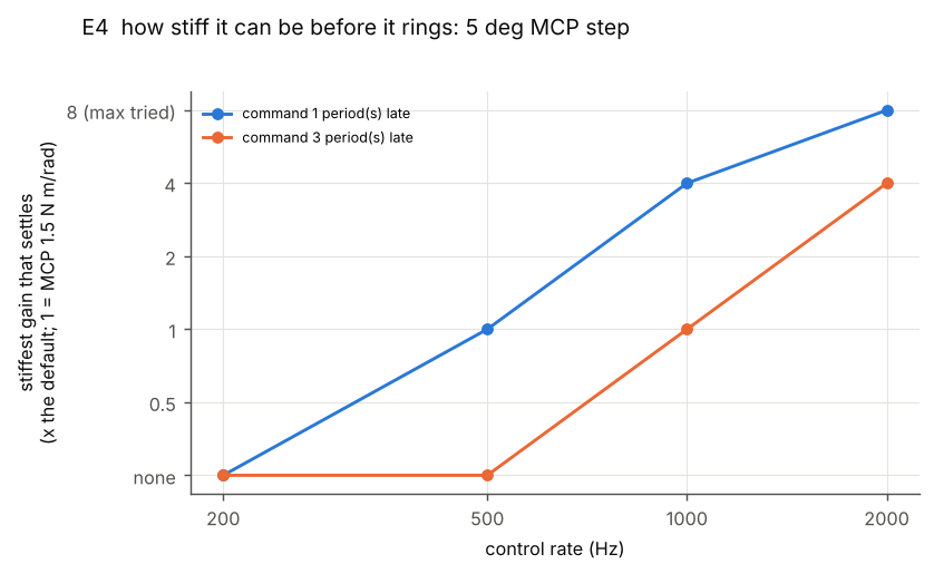
Run the loop at 1 kHz or faster.
Test: step the MCP 5° at loop rates from 200 Hz to 2 kHz, and raise the stiffness until it starts to shake.
See: each dot is the stiffest setting that still settled. 500 Hz only just handles the default; 1 kHz has 4× margin. Late commands (orange) need a faster loop.
Why: the motors are heavy (1.33 kg each at the cable), so a slow loop shakes.
E5 · channel friction
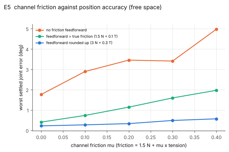
Friction feedforward cuts the error from 5° to 2°.
Test: move the finger with more and more channel friction, with and without friction feedforward.
See: no feedforward (orange) drifts to 5°. Feedforward (green) stays under 2°. Guessing friction too high (blue) is even better: under 0.6°.
Why: friction is the biggest unknown. Measure it on the bench, then round up.
E6 · the wrist moving
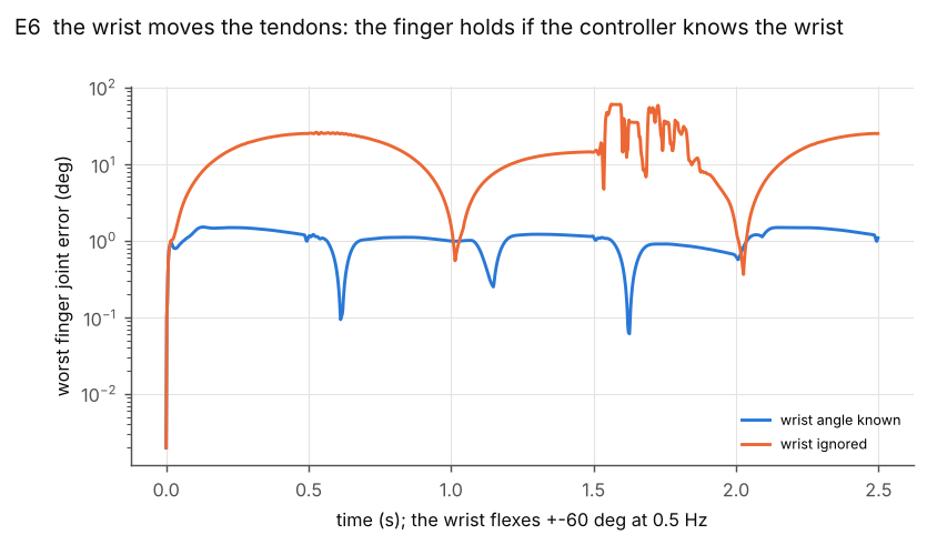
The controller must know the wrist angle.
Test: swing the wrist ±60° back and forth while the finger holds still, with and without the wrist angle.
See: without it (orange), the error repeats every swing: it drifts to ~25° as the wrist bends and back when it is straight. At the far backward swing (1.5 s) it loses track and flails (the noisy patch). With the wrist angle (blue): under 1.5°.
Why: every finger cable crosses the wrist, so bending the wrist pulls on them.
The wrist swing, on video. Left: the controller ignores the wrist. Right: it reads the wrist, and the finger holds still.
Why it drifts, then jerks:
- Smooth drift first. Bending the wrist changes every cable's length. The controller reads that as the finger moving and "corrects" it, so the finger slides to MCP 44° while the controller still thinks it is on target at 30°.
- Then the estimate breaks. At the far backward swing (−60°, at 1.5 s and 3.5 s) the cable lengths fit no pose the finger can reach, and the estimate jumps to a joint limit (spread −26°, MCP −16°).
- That is the jerk. It fights a pose that doesn't exist with huge forces: cables spike to 170–280 N, others go slack, and the finger slams between its stops.
- Then it recovers. As the wrist swings back toward straight, the cable lengths fit a real pose again.
E9 · a torque cap
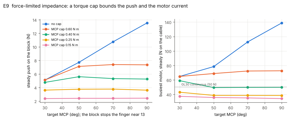
Use a 0.4 N·m torque cap.
Test: push the finger against a block, aiming further and further past it.
See: no cap (blue): the further it aims, the harder it pushes, up to 139 N in a motor. With a cap the lines go flat: 0.4 N·m gives a 5.3 N push and 50 N in the motor.
Why: it limits the grip and keeps the motors cool.
E11 · when the real finger isn't the model
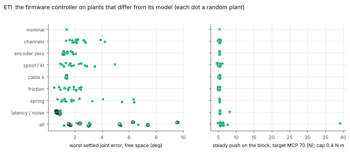
Every finger stays stable; build errors only cost accuracy.
Test: 129 fingers, each built a little wrong in one way (one row per kind of error), each making moves and then pushing a block.
See: errors reach 4–6° (left; one badly weak spring, 9.6°), all fixed by calibration and measuring the spring. The push stays at 5–6 N (right) for all but two late-command fingers. Ringed dots: commands 3 periods late, which spike a cable past 170 N, so keep latency at 2 or less.
Why: the real finger won't match the CAD exactly.
E13 · sensing the push without a force sensor
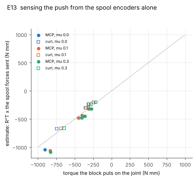
The finger can feel its push without a force sensor, to about 30 %.
Test: press the finger on a block, then compare the push it estimates from its own motor commands with the true push.
See: on the dotted line the estimate is exact. The points sit close to the line: MCP reads up to 31 % high, curl up to 24 % low.
Why: good enough to detect contact and set a grip, so no torque sensors. The grasp (E14) uses it.
E14 · a grasp
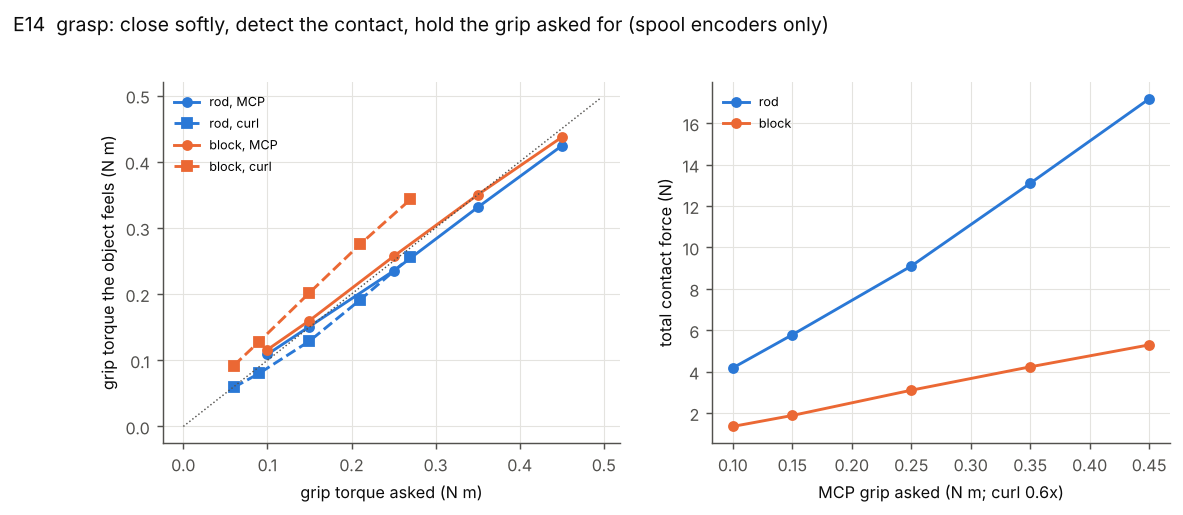
The grasp finds the object in 0.26 s and squeezes as hard as asked.
Test: close softly on a rod and a block, stop on contact, then squeeze with five grip settings.
See: on the dotted line the grip felt equals the grip asked. MCP lands within −6 / +16 %. Curl on the block is up to 53 % high, because the block rests on the curl's stop.
Why: every finger in the hand runs this.
More one-finger results
| What we did | What happened | Why it matters |
|---|---|---|
| E1 Moved the finger between targets, nothing touching it. | MCP and curl stop within 0.5° of target; spread within 1.9°. | The controller's basic accuracy. |
| E2 Told the finger to close to 70° with a block in the way at 13°. | It presses the block with 10.7 N. A stiff servo presses with 34 N and stalls two motors. | The grip force is whatever stiffness you set, not "as hard as the motors can". |
| E3 Pushed on the fingertip with ±2 N. | It gives 1 mm per 0.51 N; the design asked for 0.52. | The finger feels as soft as you set it. |
Whole hand
All four fingers and the thumb, each running the joint impedance and the grasp logic: close softly, detect contact, hold a set grip.
Holding depends on the skin's grip: the sim assumes a friction coefficient of 0.8, so measure the real cover before trusting the masses.
- Payload: a 36 mm bar holds 3 kg at 0.4 N·m grip (1 kg at 0.2 N·m) while the wrist swings ±35°.
- No slack cables: every pose can be held with all cables taut, none above 16 N, so no pose is out of control.
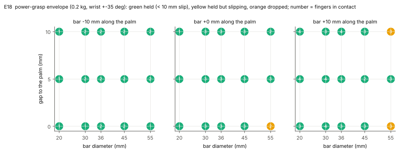
The hand held the bar in all 45 positions.
Test: place a bar at 5 sizes, 3 distances from the palm and 3 positions along it, run the same grasp, then swing the wrist.
See: green held, yellow held but slipped ~10 mm (only the 55 mm bar), orange dropped (none). The number is fingers touching.
Why: the robot only roughly knows where an object is and how big it is.
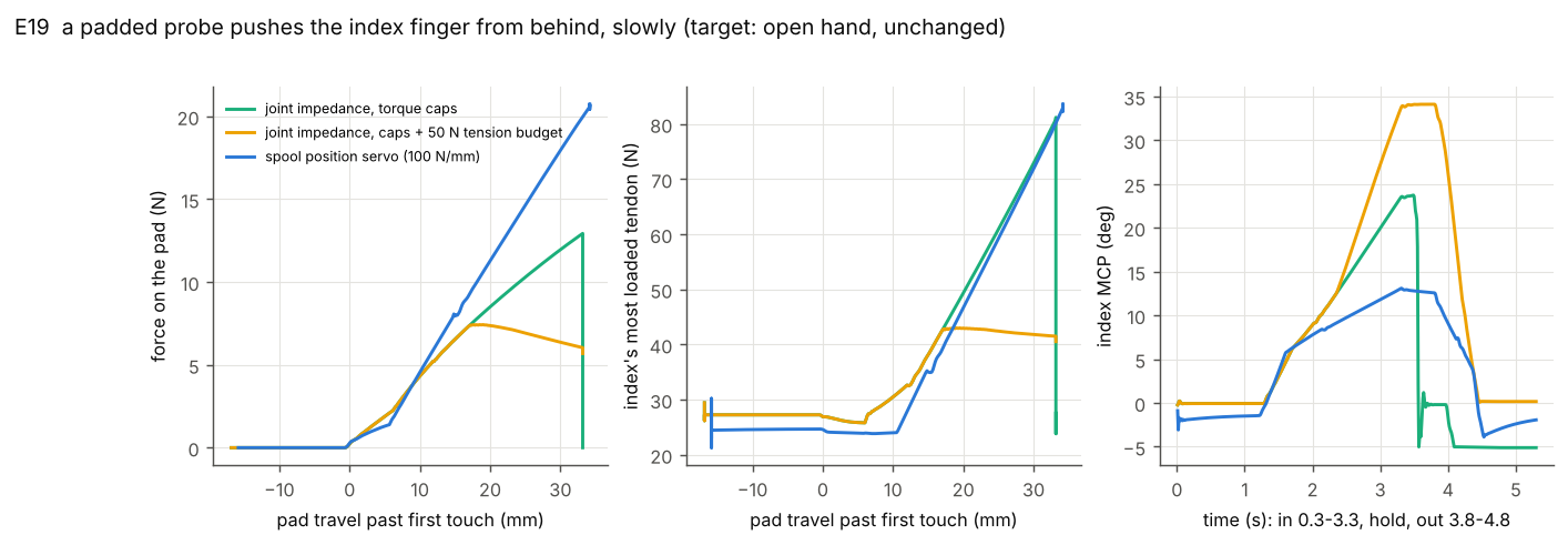
Pushed from behind, the finger gives way at 7 N. A stiff servo fights back with 21 N.
Test: push the open index finger backwards with a probe, then let go.
See: with the 50 N cable limit (yellow) the push levels off at 7.4 N and the finger bends furthest (34°), then springs back. Without the limit (green) it pushes to 13 N and snaps off. The servo (blue) pushes 21 N.
Why: a hand that gets bumped must give way.
Watch for: a finger that loses a light bar is flung by a fast wrist reversal; its curl cable spikes to ~64 N (under the 176 N peak).
Videos
A push from behind: the impedance gives way (left), a stiff servo fights (right). A probe pushes the index, then a rod presses all four fingers.
Power grasp. Close on a 100 g bar, support drops, wrist swings, a 5 N tug, release.
Pinch: a 50 g cube holds (100 g drops). Thumb and index hold the cube; the stand drops; the wrist tilts ±30° and 20° sideways. Corner plot: pad force (blue) and slip (orange).
The fingertip traces a 12 mm circle to 1.1 mm RMS, from motor encoders alone. Inverse kinematics turns the circle into MCP and PIP targets offline; the controller tracks them.
Gestures. Fist, one to five, rock, two pinches, hook and grip.
Known limits
- Loop timing: ≥ 1 kHz, ≤ 2 periods of latency. With 3 periods, the first fast move spikes a cable past 170 N (E4, E11). Keep the torque cap on: uncapped, a large step can oscillate.
- f1's cable must stay stiff. The spread is read through f1 alone: 1 mm of stretch reads as 8° of spread, and a 10 N/mm cable makes the spread shake.
- f1 holds 20–33 N all the time against the spring: 40–65 % of the GL30's continuous rating, as heat.
- Fingertip force, straight finger: 4.8 N peak, 1.3 N continuous.
- Spread accuracy is ~1.9°. MCP and curl: ~0.5° (E1).
Alternatives considered
- Differential pair for the spread (rejected). Two cables, one on each edge of the finger, ending on the proximal link past the MCP. Pulling one or the other swings the finger sideways. The problem: when the finger curls, those end points swing round with it and end up almost on the spread axis, so the cables lose their leverage. At MCP 80° a ±10° spread command reaches only +6.4 / −1.8°. The design avoids this: f1 and the spring pull on the yoke at the knuckle, which doesn't curl, so their leverage is the same at any MCP angle (+8.5 / −8.0°). The pair's one upside, more MCP strength (287 against 167 N·mm continuous), doesn't make up for it.
- Closed loop on one motor (rejected). One cable runs out and back, so one motor pulls the spread both ways. This only works if the loop's total length never changes. Bending the wrist shortens both strands by 8–23 mm, so the loop goes slack and the spread is no longer held.
Checking the model
| Check | Result |
|---|---|
| Simulation vs CAD | cable lengths within 0.035 mm, moment arms within 0.42 mm (108 poses) |
| Firmware vs simulation | cable model within 0.018 mm; C = Python firmware; both within 0.01° of the reference |
| CAD tendon check | no problems on the final geometry |
| Time step, energy, contact | results change ≤ 1 % with time step, ≤ 5 % with contact stiffness; no energy gain |
| Motor speed | the controller always stays ≥ 58 N under what the motor gives at speed |
Bench and bring-up
Do this on one finger first. System ID: measure the five numbers the simulation assumed, put them in, then run the controller at a quarter stiffness. Pass means the measured number is close enough to what the simulation assumed that its results still hold; outside the range, fix the part (or re-run the simulation with the measured value) before going on. The firmware always uses the measured numbers. Follow the arm's hardware-safety process for every powered step.
Next steps
| Need | Status |
|---|---|
| One finger built per the CAD: 4 GL30s, spools, cables, cross-cable, spread spring | to build |
| A motor driver per GL30: current control and a speed mode, encoder readout, ≥ 1 kHz | not chosen yet |
| Logging per motor, every period: time, commanded cable force, spool travel, spool speed | to write |
| Hardware E-stop on the motor supply, within reach | to fit |
| Weights (0.5 / 1.5 / 3 / 5 kg, 10–25 N), a clamp, calipers, and an angle reference (jig, camera or clip-on encoders) | to get |
Phase 1 · set up
- Mount the finger pointing down. E-stop in reach. Current limit 60 N at the cable (0.095 N·m at the motor), speed limit 5 mm/s. Pass: the E-stop cuts all four motors.
- Check the encoders, motors off. Turn each spool by hand. Pass: winding in reads +, 1 mm of cable reads 1 mm, and f1 moves the spread, f2 the MCP, f3 curls, f4 straightens.
Phase 2 · system ID
- Friction and force scale sys ID, per cable. Unhook the cable at the fingertip and hang a weight on it, so it still runs through every channel. Hang 0.5 / 1.5 / 3 / 5 kg in turn, wind in then pay out at 2 mm/s. Lifting takes weight + friction, lowering takes weight − friction. Fit: friction = half the difference; plot it against weight: intercept = f0, slope = mu. Mean force ÷ weight = force scale. Pass: mu ≤ 0.3, force scale 0.8–1.2.
- Cable stiffness sys ID, per cable. Hook the cable back on, clamp the finger so it can't move, ramp the force 0 → 50 N. Any spool travel is now the cable stretching. Fit: plot spool travel against force; 1 ÷ slope = stiffness. Pass: 30–120 N/mm.
- Latency sys ID. Slack cable, 1 N step. Fit: time to the first encoder count ÷ control period. Pass: ≤ 2 periods at 1 kHz.
- Spring sys ID, before fitting it. Hang the spring from a hook, hang 10 / 15 / 20 / 25 N on it, and measure its length with calipers each time. Fit: draw a straight line through force against length. Its slope is the spring rate (N per mm of stretch). Read the line at 29.4 mm, the spring's length in the hand: that force is the preload. Pass: rate 1.3–1.7 N/mm, preload 16–20 N.
Phase 3 · tune and run
- Enter the numbers into the firmware: friction (round up), force scale, cable stiffness, latency, spring rate and preload.
- Power one cable at a time at 5 N, finger free. Pass: each joint moves as in phase 1, nothing else moves.
- Cable-model sys ID (calibration). Run the 48 poses (spread −10 / 0 / 10°, MCP and curl 0 / 30 / 60 / 85°), logging reference angles, spools and tensions. Fit: a small polynomial correction to the finger's cable model. Pass: residuals ≤ 0.05 mm. In sim this takes a finger built 0.3 mm off the CAD from up to 5.1° of error to 1.5°.
- Run the controller at a quarter stiffness (75 / 375 / 200 N·mm/rad) and a 0.1 N·m cap: hold, then small moves. Pass: settles within ~2°, gives way by hand, no buzzing. Then step up to full stiffness and the 0.4 N·m cap.
Not covered by calibration: Dyneema creep (re-zero against the stops periodically), slip on the spool, gear backlash, encoder resolution (aim for ~0.01 mm of cable).