TVC Rocket: A Technical Deep Dive
A spinoff from the WATonomous Humanoid team: a thrust-vector-controlled (TVC) rocket. Here's how it works.
What is TVC?
Have you ever wondered how NASA or SpaceX control their rocket during flight? For a small model rocket, the most straightforward option is fins — just let the airflow keep the rocket pointed straight. But fins get impractical once you're at large scale: no airflow, no control, and they're just extra drag and weight you're dragging along.
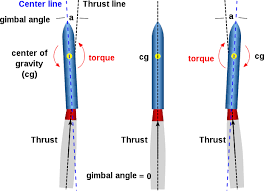
So instead, big rockets use thrust vector control (TVC). The idea is simple: you control where the thrust points, and use the horizontal component of that thrust to generate a torque that controls the rocket's orientation. Tilt the engine a few degrees off-center, and now part of that thrust is pushing sideways instead of straight down — and since it's acting away from the rocket's center of mass, it rotates the rocket. Doesn't matter how fast (or slow) you're going, it still works, which is why it's the go-to for landings too, not just ascent.
Meet Pioneer
The long term goal here is propulsive landing — bringing the rocket back down under its own thrust, SpaceX-style, or eventually even catching it out of the air like Starship's booster does with the tower's "chopsticks." Both of those are really just TVC problems taken further, needing control through a much harder flight regime than ascent.
Pioneer, the rocket in the video above, only has to nail one thing: ascent. Stable, controlled powered flight. Landing and catching come once that's solid.
The control algorithm
So the first thing you're probably wondering is: what's actually driving the gimbal? This is where it gets technically kind of hairy.
Two things are working against us:
- We're using solid rocket motors — the impulse is huge the moment it lights, and once it's lit, that's it, you can't throttle it or shut it off.
- Every launch burns exactly one motor. There's no re-testing on the cheap — if the controller doesn't work, you don't get a redo, you just wasted a motor.
Put those together and you get a lot of pressure to have the control method figured out before it ever leaves the ground. The solution we went with is honestly just PID control, and it works surprisingly well even under these constraints.
The ping-pong ball analogy
Easiest way to think about PID: balancing a ping-pong ball on a racket, trying to keep it centered.
-
P (Proportional) — as the ball gets further from center, you'd naturally tilt the racket more to bring it back. That's proportional control: you tilt based on how far off-center the ball currently is. Bigger offset, bigger tilt.
-
D (Derivative) — if the goal is to have the ball sitting still at the center, position alone isn't enough. You also watch how fast it's moving toward the center, and pre-emptively tilt against that motion so it slows down and settles right at the center instead of flying past it.
-
I (Integral) — if the ball keeps drifting the same way over time (say your racket's slightly tilted to begin with), you accumulate that error and correct for the persistent bias — something P alone can't fix.
Worth noting: not every real controller actually uses all three terms. A lot of actuator-driven systems run PD instead of full PID — the integral term can cause "windup" issues once the actuator saturates (maxes out), where the buildup causes a big overshoot once it un-saturates. For a fast gimbal that's often close to its deflection limits, that tradeoff usually isn't worth it, so some setups skip the I term entirely.
Applying it to the rocket
Same principle, just applied to the rocket instead of a ball. Instead of position, the error term is the gap between desired and actual pitch/yaw angle:
The PID controller turns that error into a commanded gimbal deflection angle :
And that commanded angle turns into actual torque on the rocket through the gimbal geometry:
where is the thrust force, is the gimbal deflection angle, and is the distance from the gimbal pivot to the rocket's center of mass. Tune , , and right, and that torque is what keeps the rocket pointed where it should be throughout the burn, correcting for disturbances in real time.
Airframe and avionics
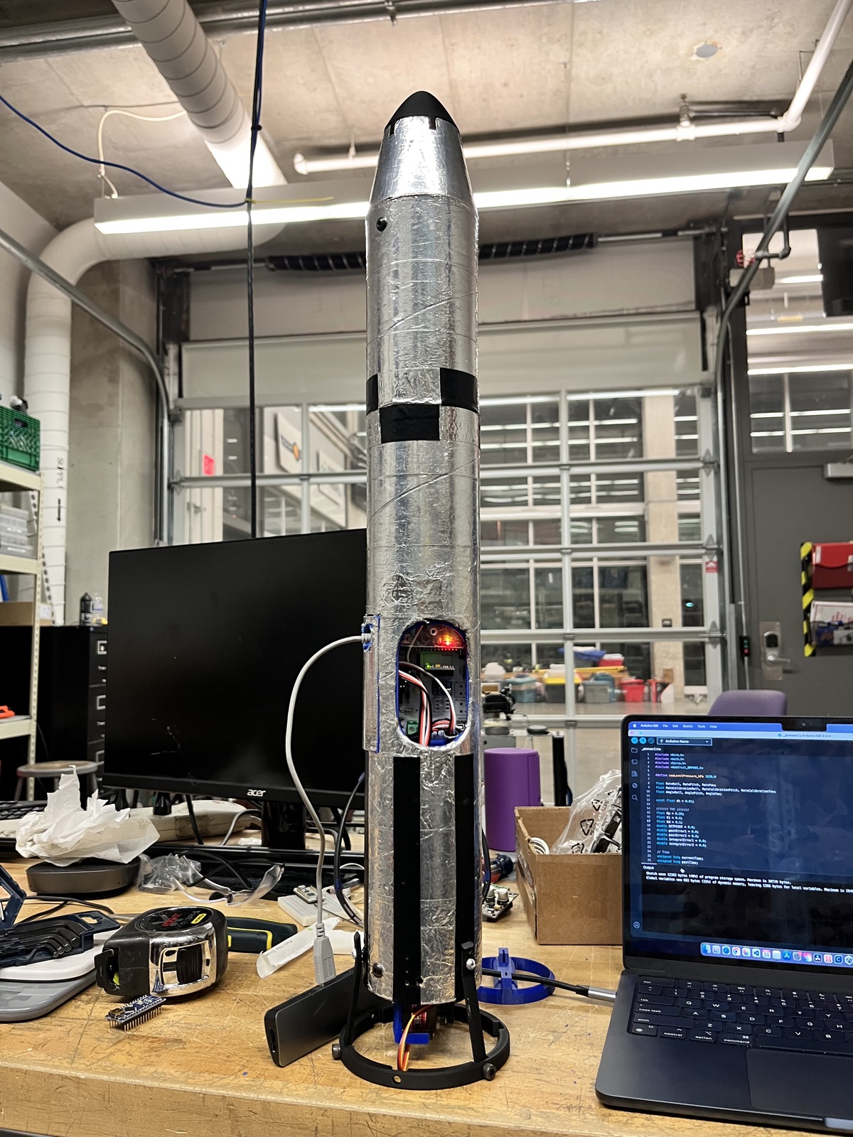
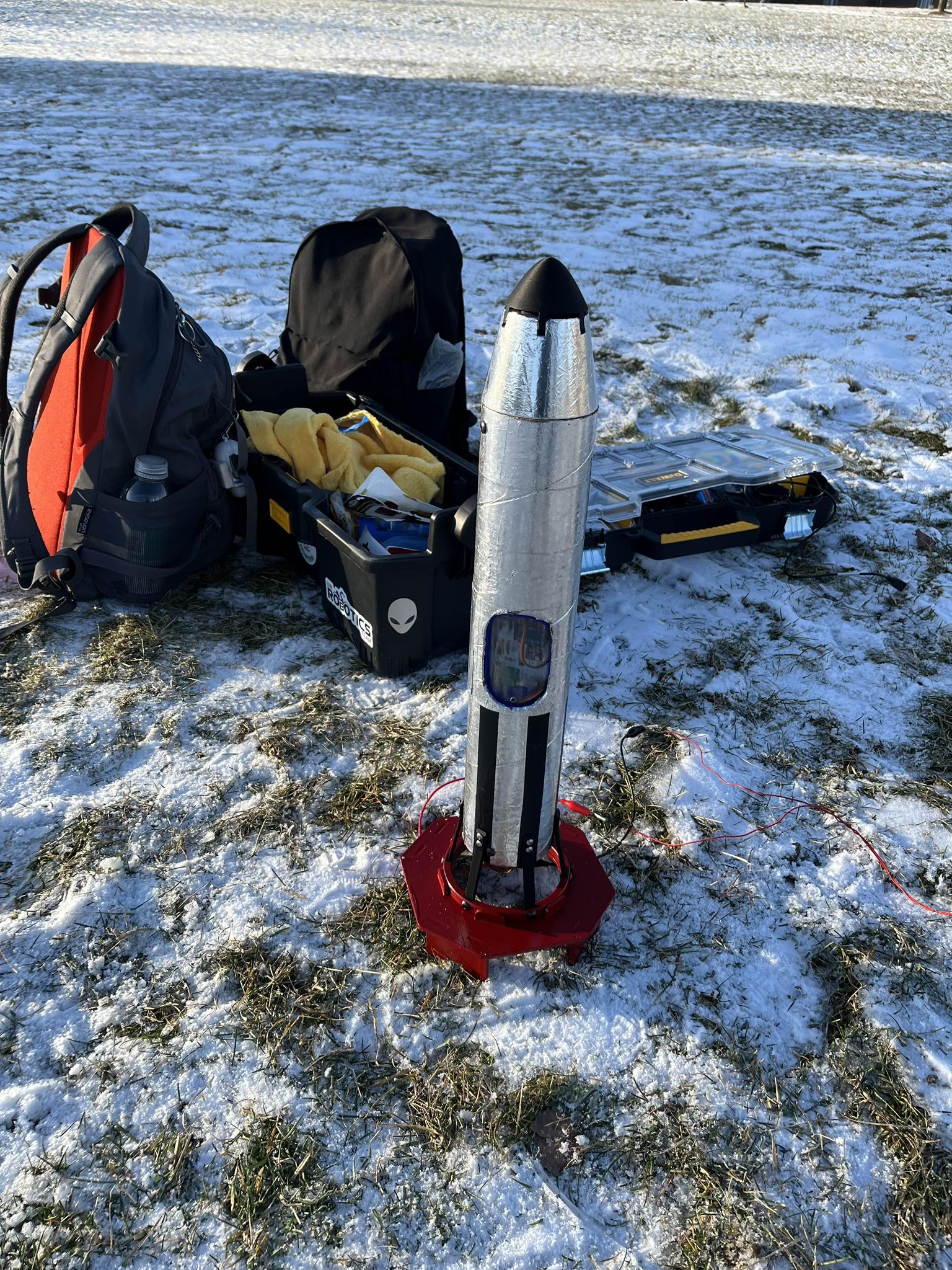
The body's a foil-wrapped tube with a 3D-printed nose cone, but the part that actually matters is the gimbal mount at the base: a printed bracket holding two servos at 90° to each other, one for pitch and one for yaw, so the motor can be pushed off-axis in any direction.
Flying the electronics is a custom PCB — Arduino Nano as the flight computer, an MPU6050 for rate/angle data (that's what feeds the PID loop) and a BMP180 barometer. All of it sits in a bay cut into the body tube, wired straight to the servos.
Testing, one milestone at a time
Since a real launch is a one-shot, motor-consuming event, we can't just wing it and see what happens. Instead there's a staged pipeline, each step cheaper and safer to fail at than the next:
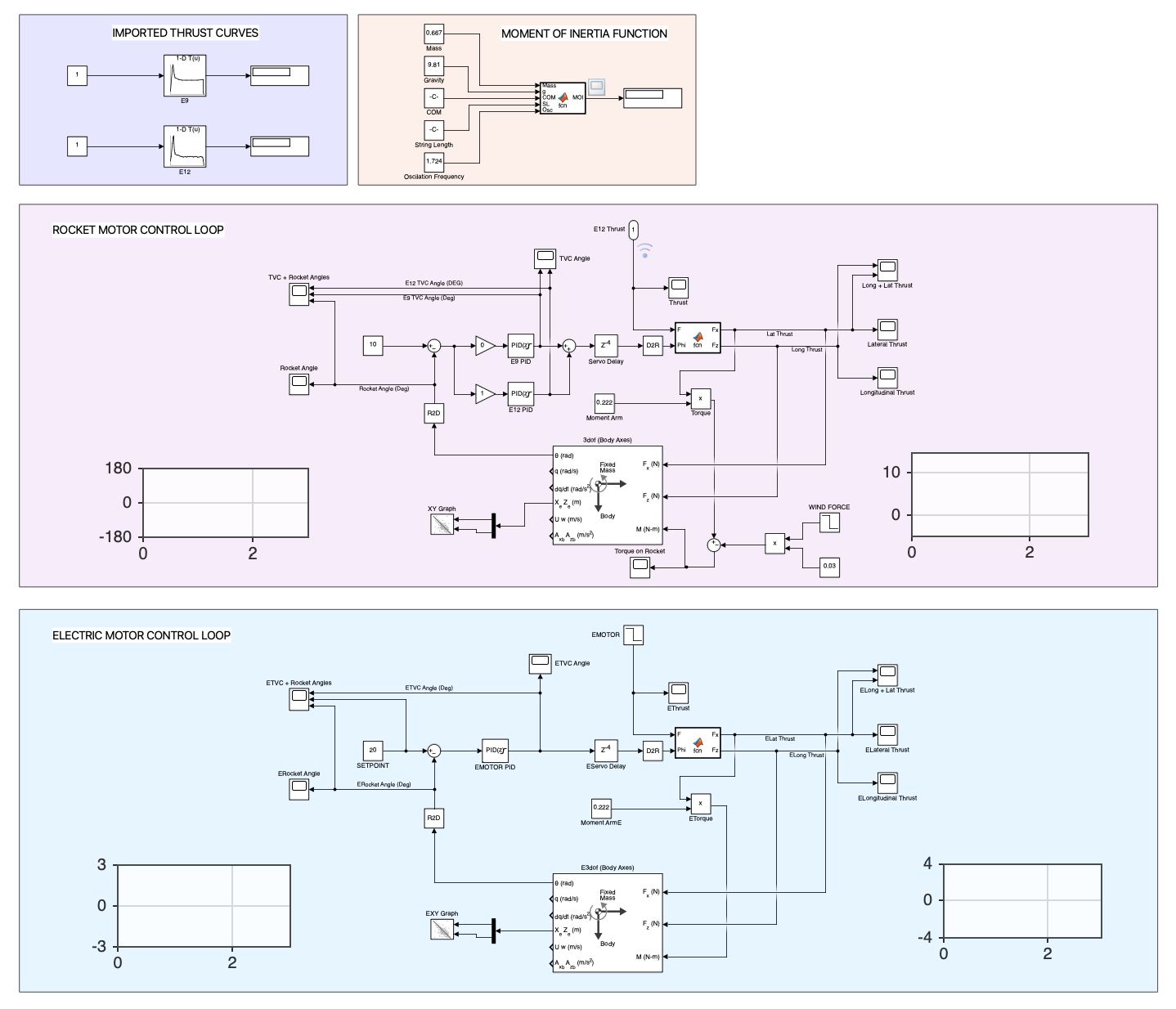
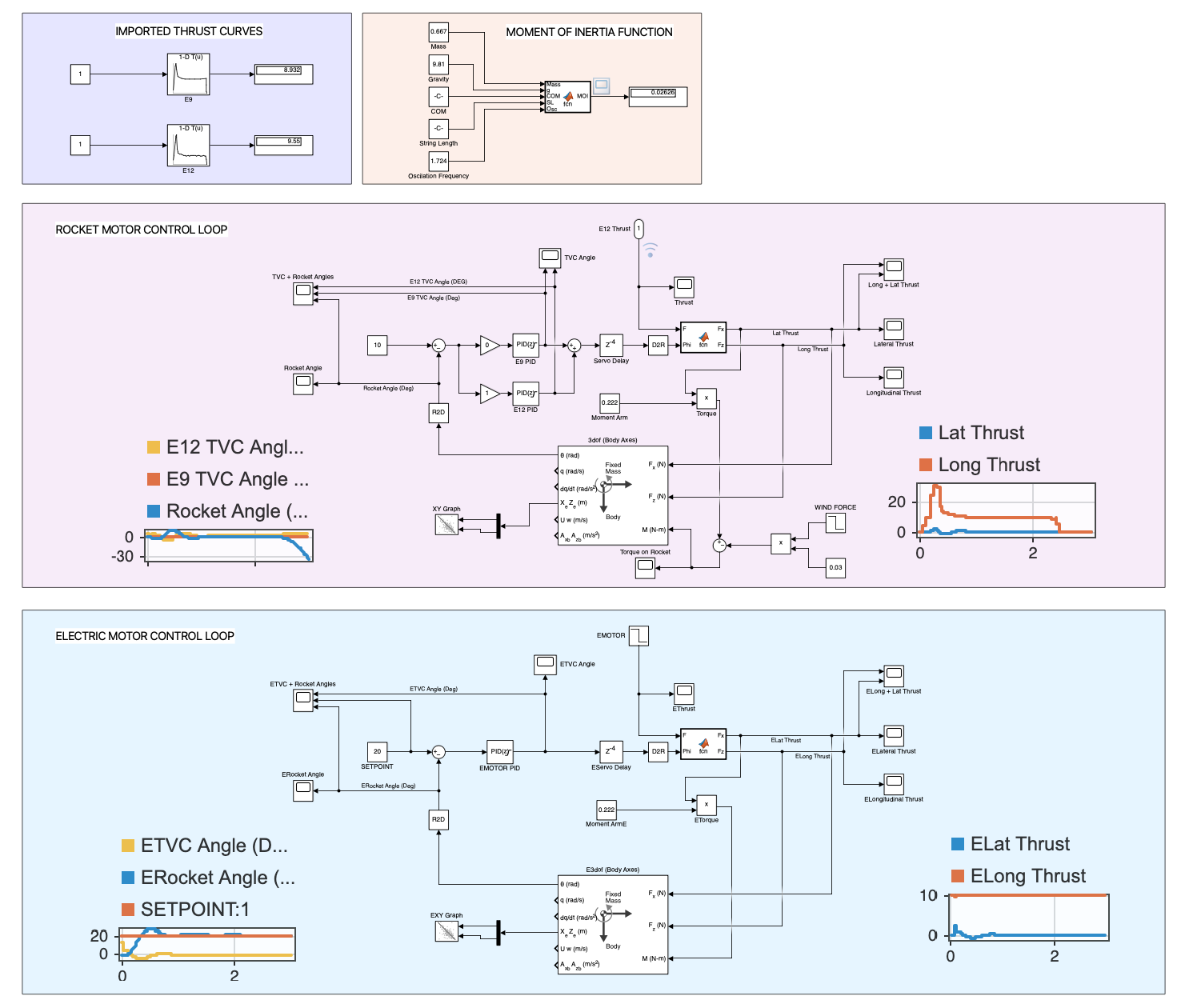
- MATLAB/Simulink simulation — check the control loop and gains actually work against a simulated rocket, before touching hardware.
- BLDC test bench — get the gimbal actuator and control loop timing working on the bench, driven by a BLDC motor instead of a real rocket motor.
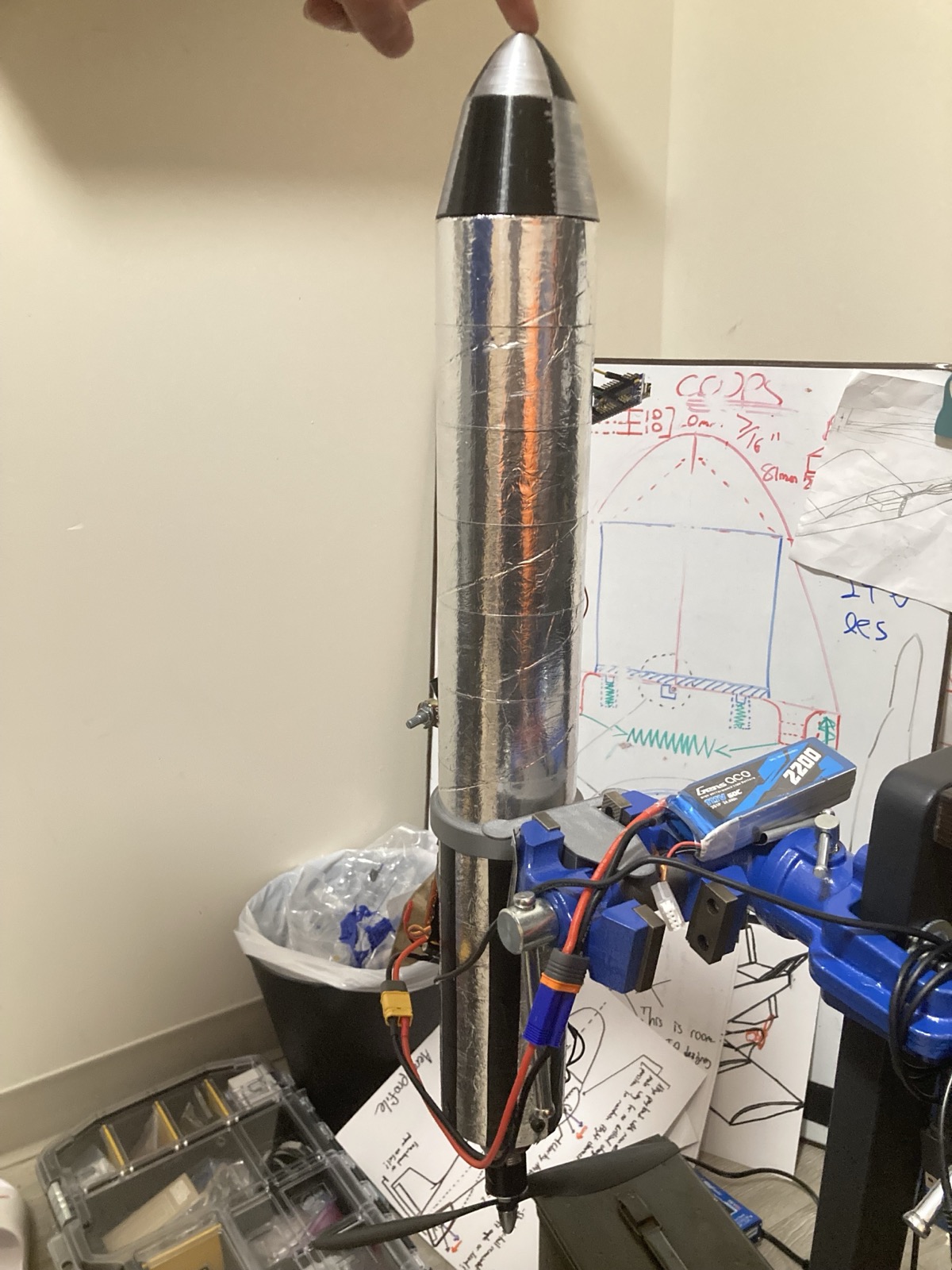
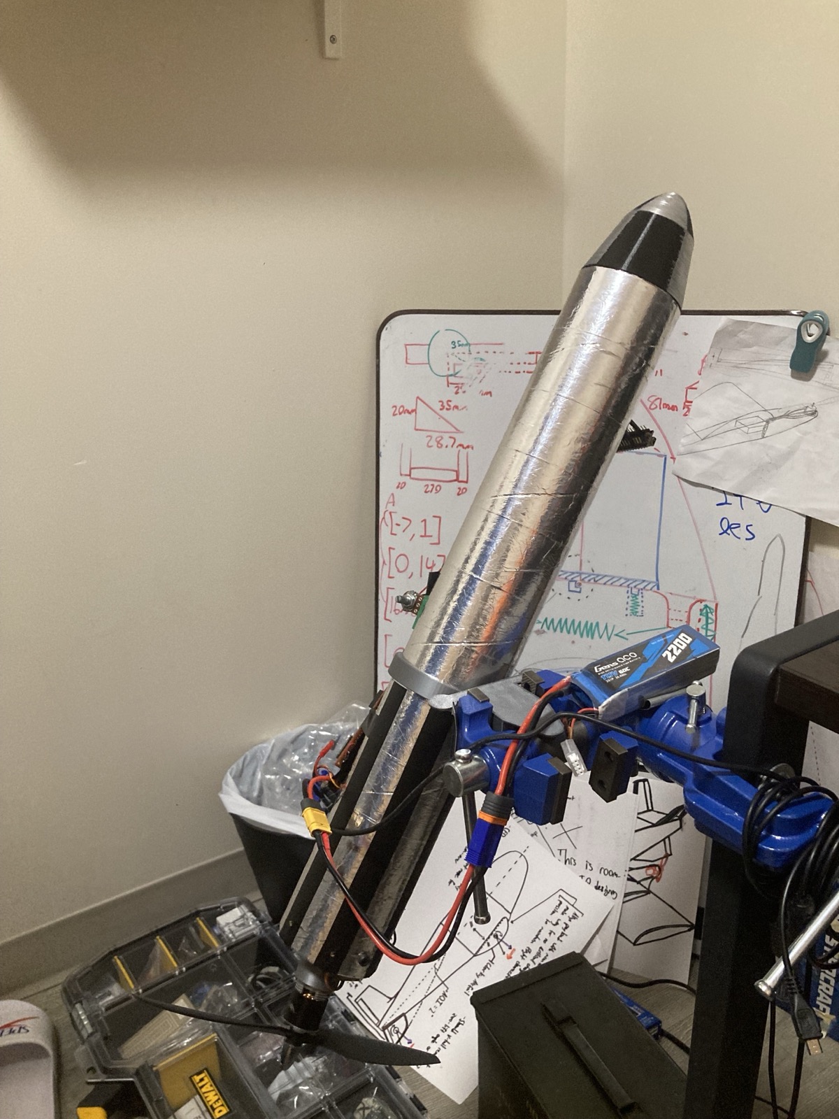
- Motor test bench static fire — full control loop, real motor, but static-fired on a stand so we can measure thrust and gimbal response without an actual flight.
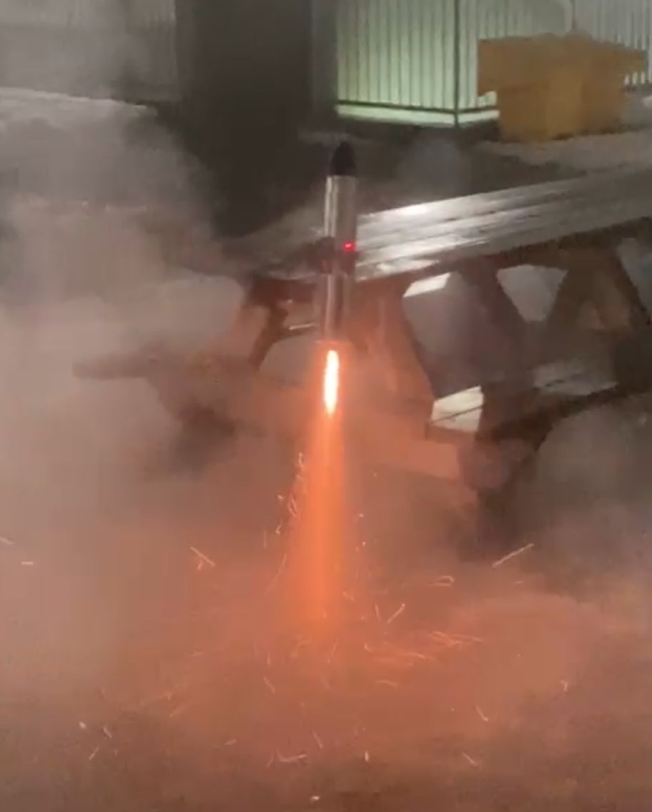
- Actual flight test — Pioneer leaves the pad.
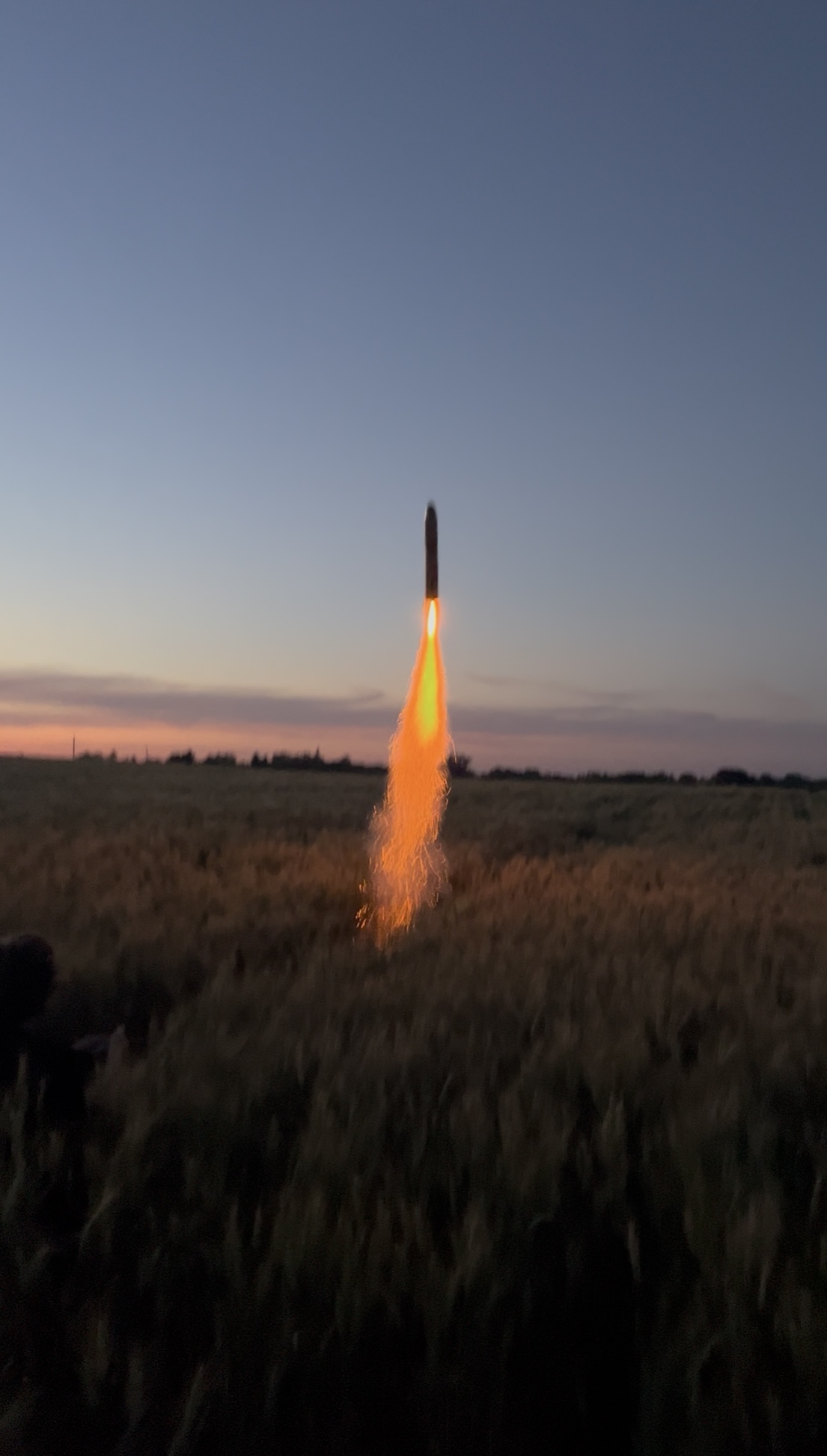
Results
After all the vigorous testing, we got two consecutive successful launches!