Electrical
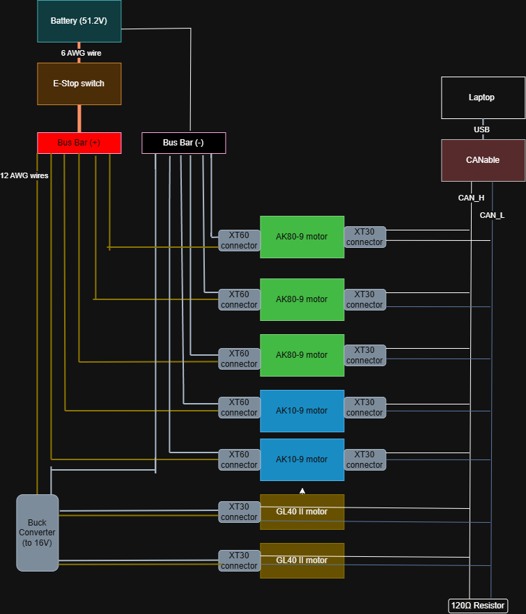
This page documents the power distribution and CAN bus wiring for the 6 DOF arm. The system is powered by a 51.2 V battery and controlled over CAN from a laptop via a CANable USB adapter.
Overview
| Subsystem | Description |
|---|---|
| Power source | 51.2 V battery |
| Safety | E-stop on the positive rail |
| High-voltage motors | 3× AK80-9, 2× AK10-9 at 51.2 V |
| Low-voltage motors | 2× GL40 II at 16 V (via buck converter) |
| Communication | Shared CAN bus (CAN_H / CAN_L), terminated with 120 Ω |
Power Distribution
Battery and bus bars
Power flows from the 51.2 V battery through an E-stop switch on the positive side, then to a Bus Bar (+). The battery negative connects directly to Bus Bar (−).
| Connection | Wire gauge |
|---|---|
| Battery (+) → E-stop | 6 AWG |
| E-stop → Bus Bar (+) | 6 AWG |
| Bus Bar (+) → loads | 12 AWG |
| Battery (−) → Bus Bar (−) | 6 AWG |
Motor power
Five motors run directly from the 51.2 V bus bars via XT60 connectors:
| Motor | Quantity | Voltage | Connector |
|---|---|---|---|
| AK80-9 | 3 | 51.2 V | XT60 |
| AK10-9 | 2 | 51.2 V | XT60 |
Two GL40 II motors operate at a lower voltage. A buck converter steps the 51.2 V bus down to 16 V, which is delivered to both motors via XT30 connectors.
| Motor | Quantity | Voltage | Connector |
|---|---|---|---|
| GL40 II | 2 | 16 V | XT30 |
These motors correspond to the 6 DOF arm motor selection: AK10-9 at the shoulder, AK80-9 at the elbow joints, and GL40 at the wrist and gripper.
Power Distribution Unit (PDU)
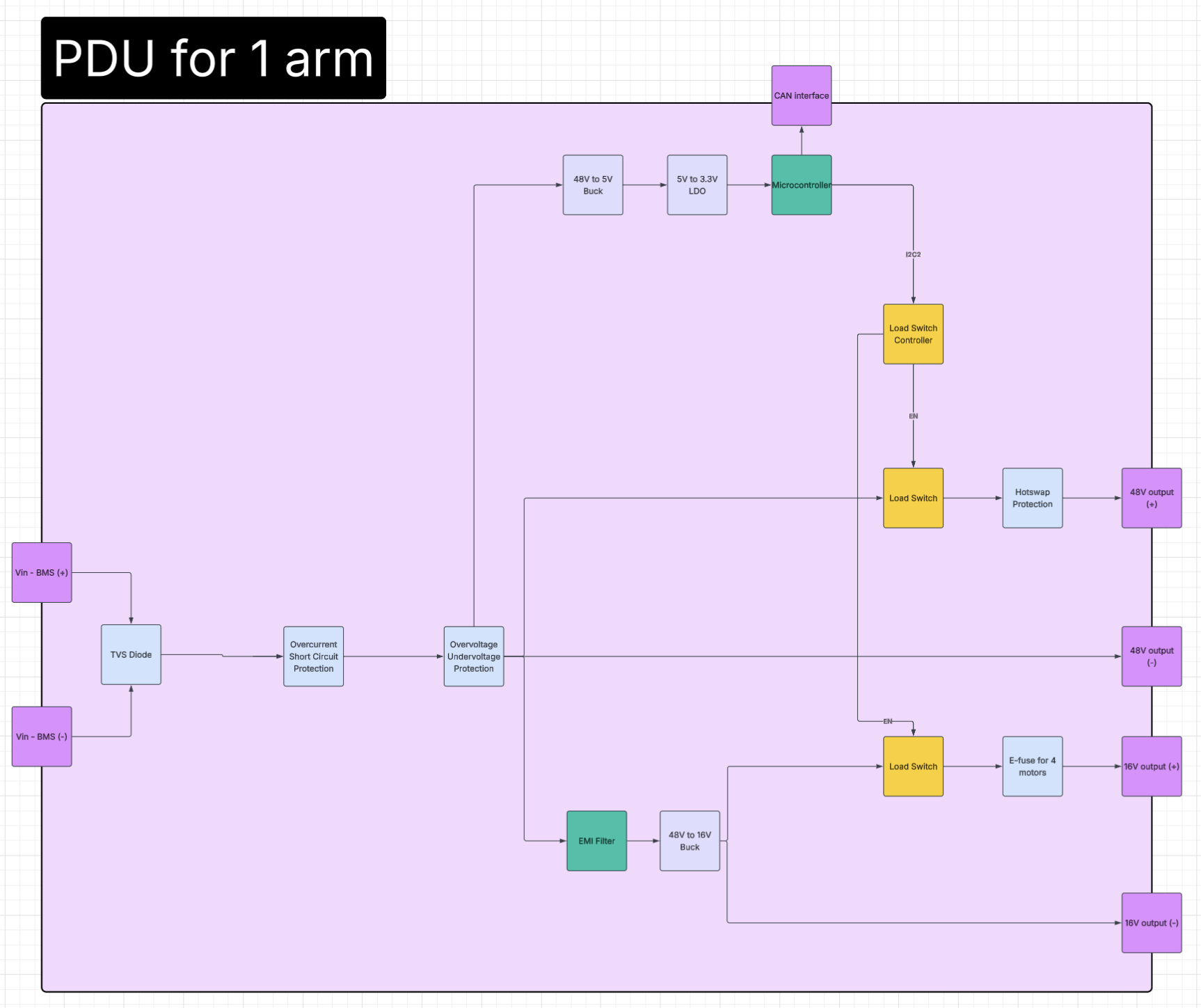
A custom PDU is being designed for one arm. It replaces the bare bus bar setup with input protection, switched and protected outputs, and a microcontroller that reports over CAN.
Planned PDU layout
For now, the full humanoid is planned to use four PDUs, one per limb, plus an optional auxiliary power board:
| Board | Count | Powers |
|---|---|---|
| Arm PDU | 2 | One per arm (left and right) |
| Leg PDU | 2 | One per leg (left and right) |
| Auxiliary power board (optional) | 1 | Extra loads such as the RealSense camera, the Jetson, and possible future waist yaw actuators |
The block diagram below shows the arm PDU.
Input protection
The battery input (Vin – BMS (+) and Vin – BMS (−)) passes through three protection stages before reaching any load:
| Stage | Purpose |
|---|---|
| TVS diode | Clamps voltage transients and spikes on the input |
| Overcurrent / short circuit protection | Cuts power on excessive current draw or a short |
| Overvoltage / undervoltage protection | Disconnects the rails when the input leaves the safe voltage window |
Logic power and control
| Block | Function |
|---|---|
| 48 V → 5 V buck | Steps the protected input down to 5 V |
| 5 V → 3.3 V LDO | Provides a clean 3.3 V rail for the logic |
| Microcontroller | Monitors the board and commands the output load switches |
| CAN interface | Connects the microcontroller to the arm CAN bus |
| Load switch controller | Driven by the microcontroller over I²C; drives the EN pins of both load switches |
Outputs
| Output | Path | Loads |
|---|---|---|
| 48 V (+ / −) | Load switch → hotswap protection → output | AK80-9 and AK10-9 motors |
| 16 V (+ / −) | EMI filter → 48 V to 16 V buck → load switch → e-fuse → output | GL40 II motors (e-fuse sized for 4 motors) |
- Load switches let the microcontroller enable or disable each rail independently.
- Hotswap protection on the 48 V rail limits inrush current when motors are connected or the rail is enabled.
- The EMI filter ahead of the 16 V buck keeps switching noise off the main 48 V rail.
- The e-fuse on the 16 V rail provides fast overcurrent protection for the low-voltage motors.
CAN Bus
All seven motors share a single CAN network for command and feedback.
Controller
A laptop connects over USB to a CANable adapter, which drives the bus.
Wiring
| Line | Function |
|---|---|
| CAN_H | CAN high |
| CAN_L | CAN low |
Each motor taps into CAN_H and CAN_L via XT30 connectors. The bus is terminated at the end with a 120 Ω resistor to prevent signal reflections.
Connector Summary
| Connector | Use |
|---|---|
| XT60 | 51.2 V power to AK80-9 and AK10-9 motors |
| XT30 | 16 V power to GL40 II motors; CAN data on all motors |
Wire Gauge Summary
| Application | Gauge |
|---|---|
| Main power (battery to E-stop, E-stop to bus bar) | 6 AWG |
| Distribution (bus bar to motors and buck converter) | 12 AWG |