watonomous.github.io
[ Electrical Division : Radar Power Design ]
Created by [ Mitchell Hoyt], last modified by [ Jack Marlow] on Nov 02, 2020
- Research Requirements and Limitations for use of the Radar and
Battery:
- Use research resources (ie. Autodrive, plus existing documents) to find critical information and limitations of the Radar and the Battery (ie. current draw, how fast can the voltage rise, etc) → Create/ Add on findings to existing Radar Documentation
- Discuss with mechanical about installation limitations. (ie. how we will route the wires and placement on the compute rack)
- Research secure connection options for design
- Do simulations with LTSpice with some circuit design ideas, consider
things such as heat, power consumption etc
- Develop specific document showing tests that need to be completed and expected results (Based on Step 1): ie. Voltage rise allowed, expected fluctuations, etc.
- Develop results document, analyze the results and see if it works with the radar.
- Draw schematic
- Develop PCB layout with proper connectors for the radar, this should be researched
Voltage Converter Specs
\
Min
Nom
Max
Unit
Input Voltage
4.5
\
30
V
Output Voltage
0.5
\
30
V
Voltage Ripple
20
\
30
mW
Output Current Limit
\
\
3
A
Power Limits
\
\
30
W
Efficiency (Step down)
87
\
90
\%
Efficiency (Step up)
88
\
91
\%
Frequency
\
180
\
kHz
Converter Dimensions - 48*23*21mm (Note Voltage converter suggested has no datasheet that we can find, looking into other options that give more details)
https://www.amazon.ca/dp/B07S3WSBCD/ref=cm_sw_r_oth_api_i_K1d1DbQX93WHV#detail_bullets_id ———————————————————————————————
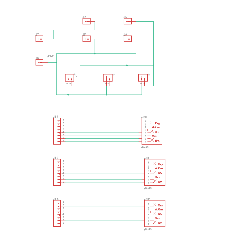
Radar PCB Rev. 0 - Designer: Jack
Image:
[ {.confluence-embedded-image
height=”400”}]{.confluence-embedded-file-wrapper
.confluence-embedded-manual-size}[
{.confluence-embedded-image
height=”400”}]{.confluence-embedded-file-wrapper
.confluence-embedded-manual-size}[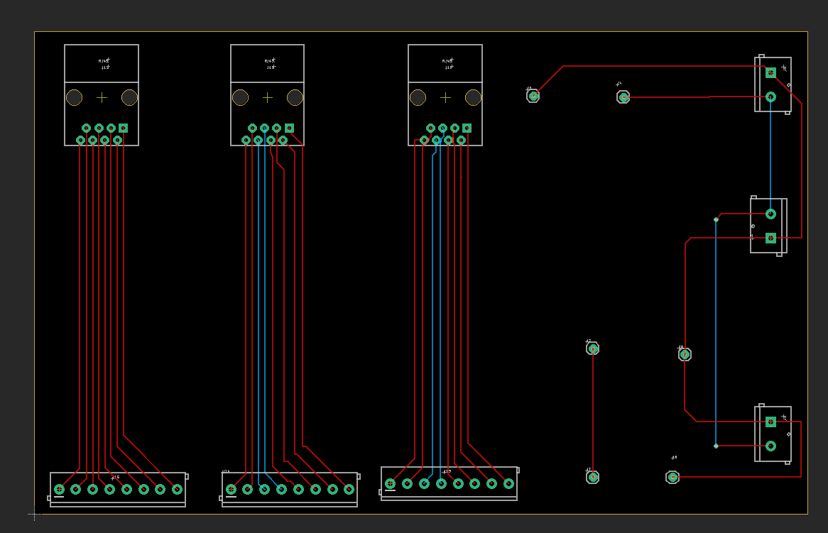 {.confluence-embedded-image
height=”400”}]{.confluence-embedded-file-wrapper
.confluence-embedded-manual-size}
{.confluence-embedded-image
height=”400”}]{.confluence-embedded-file-wrapper
.confluence-embedded-manual-size}
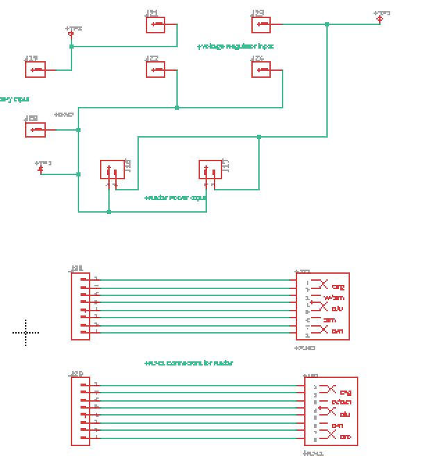
Radar PCB Rev. 1 - Designer: Jack
[ {.confluence-embedded-image
height=”400”}]{.confluence-embedded-file-wrapper
.confluence-embedded-manual-size}[
{.confluence-embedded-image
height=”400”}]{.confluence-embedded-file-wrapper
.confluence-embedded-manual-size}[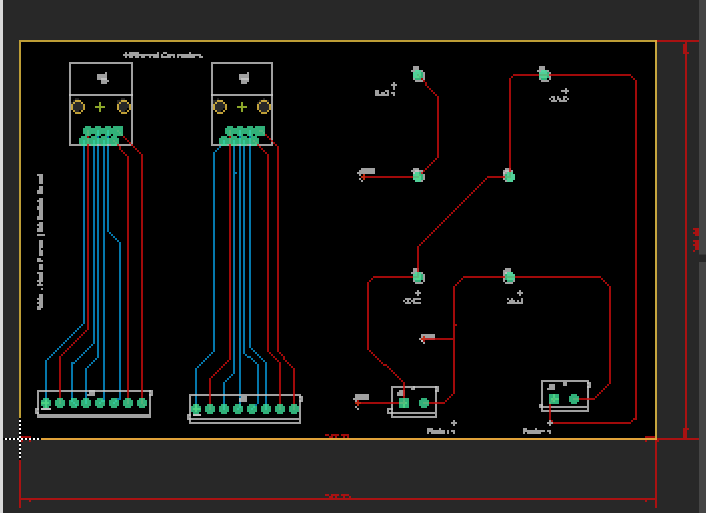 {.confluence-embedded-image
height=”400”}]{.confluence-embedded-file-wrapper
.confluence-embedded-manual-size}
{.confluence-embedded-image
height=”400”}]{.confluence-embedded-file-wrapper
.confluence-embedded-manual-size}
Board Dimensions:
100mm x 160mm
Required Parts:
Part Description (RefDes Associated) Amazon Link —————————————- —————————— J13, J14, J15 - 8 Pin Connector \
J1, J5, J6 - 2 Pin Connectors We should have already
J2, J3, J6, J7, J8, J9 - TBD (either
1Pin Header or Screws)
J10, J11, J12 - RJ45 Connectors
———————————————————————–
Question: How do we create the proper connection to connect to the car directly? Does a Screw Terminal work? Do we require any Mounting Holes in the PCB?
Rev1 Planned Changes: Jack Marlow{.confluence-userlink .user-mention}
- Add a Silkscreen
- Add Test Points
- Only set up for 2 radars
- Screw Terminals are okay for connecting the PCB to the Car
- Check Radar Setup to verify connections
\
\
Attachments:
![]() image2020-9-25_20-47-46.png
(image/png)
image2020-9-25_20-47-46.png
(image/png)
![]() image2020-9-25_20-48-10.png
(image/png)
image2020-9-25_20-48-10.png
(image/png)
![]() image2020-11-2_18-13-7.png
(image/png)
image2020-11-2_18-13-7.png
(image/png)
![]() image2020-11-2_18-13-48.png
(image/png)\
image2020-11-2_18-13-48.png
(image/png)\
Document generated by Confluence on Nov 28, 2021 22:40